Radar
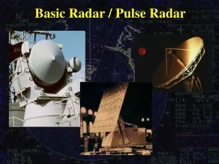
Radar. OUTLINE History Applications Basic Principles of Radar Components of a Pulse Radar System The Radar equation Moving Target Indicator (MTI) radar. Radar. History Invented in 1900s (patented in 1904) and reinvented in the 1920s and 1930s


Radar
E N D
Presentation Transcript
Radar OUTLINE • History • Applications • Basic Principles of Radar • Components of a Pulse Radar System • The Radar equation • Moving Target Indicator (MTI) radar ELEC4600 Radar and Navigation Engineering
Radar • History • Invented in 1900s (patented in 1904) and reinvented in the 1920s and 1930s • Applied to help defend England at the beginning of World War II (Battle of Britain) • Provided advance warning of air raids • Allowed fighters to stay on ground until needed • Adapted for airborne use in night fighters • Installed on ships for detecting enemy in bad weather (Bismarck) ELEC4600 Radar and Navigation Engineering
Radar-Applications • Air Traffic Control • Air Navigation • Remote Sensing • Marine • Law Enforcement and highway safety • Space • Military ELEC4600 Radar and Navigation Engineering
Radar-Applications • Air Traffic Control • Monitor the location of aircraft in flight • Monitor the location of aircraft/vehicles on surface of airports • PAR (precision approach radar) • Guidance for landing in poor weather ELEC4600 Radar and Navigation Engineering
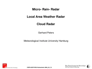
Radar-Applications • Air Navigation • Weather radar • Terrain avoidance and terrain following • Radar altimeter • Doppler Navigator ELEC4600 Radar and Navigation Engineering
Radar-Applications • Remote Sensing • Weather observation • Planetary observation (Venus probe) • Mapping • Ground Penetration radar ELEC4600 Radar and Navigation Engineering
Radar-Applications • Marine • Detecting other ships, buoys, land • Shore-based radar for harbour surveillance and traffic control • Law Enforcement and highway safety • Traffic speed radar • Collision warning • Blind area surveillance for cars and school buses • Intrusion alarms ELEC4600 Radar and Navigation Engineering
Radar-Applications • Space • Rendezvous and docking • Moon landing • Remote Sensing (RADARSAT) ELEC4600 Radar and Navigation Engineering
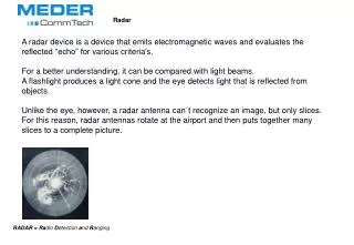
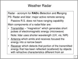
Radar • Basic Principles • Transmits an electromagnetic signal modulated with particular type of waveform. (modulation depends on requirements of application) • Signal is reflected from target • Reflected signal is detected by radar receiver and analyzed to extract desired information ELEC4600 Radar and Navigation Engineering
Radar • Modulation Types • Simple Pulse; one or more repetition frequencies • Frequency Modulation FM (radar altimeters) • Pulse with Chirp (pulse compression) • CW (continuous wave) - police radar (Doppler) • Pseudorandom code ELEC4600 Radar and Navigation Engineering
Radar • Basic Principles • Distance can be determined by measuring the time difference between transmission and reception • Angle (or relative bearing) can be determined by measuring the angle of arrival (AOA) of the signal (usually by highly directive antenna) • If there is a radial component of relative velocity between radar and target it can be determined from the Doppler shift of the carrier ELEC4600 Radar and Navigation Engineering
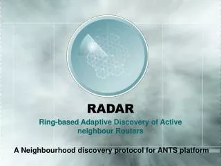
Radar • Basic Principles • Two types of radar:Monostatic - transmitter and receiver use same antenna • Bistatic - transmitter and receiver antennas are separated, sometimes by large distances ELEC4600 Radar and Navigation Engineering
Radar • Generic Radar System Local Oscillator ELEC4600 Radar and Navigation Engineering
Radar - Generic System Transmitter Magnetron, Klystron, or a solid state oscillator followed by power amplifiers Power levels: Megawatts peak, several kW average Duplexer or Isolator To keep the power from the transmitter from entering the receiver. E.g. 2MW output, .1 pW input Ratio: 1019 or 190 dB IF Amplifier/Matched Filter ELEC4600 Radar and Navigation Engineering
Radar - Generic System Detector: Extracts the modulation pulses which are amplified by the video amplifier Threshold Decision: Determines whether or not a return has been detected ELEC4600 Radar and Navigation Engineering
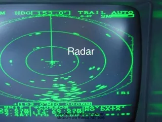
Radar - Generic System Display: Usual display is a plan position indicator (PPI) ELEC4600 Radar and Navigation Engineering
Radar • The Influence of LNA (low noise amplifier) • an LNA is not always beneficial since it decreases the dynamic range (DR) of the receiver • DR is the difference between • the maximum signal which can be processed (usually determined by the compression level of the mixer) • The minimum detectable level determined by the noise power • The tradeoff is between sensitivity and dynamic range ELEC4600 Radar and Navigation Engineering
Radar (LNA) Input to Mixer ELEC4600 Radar and Navigation Engineering
Radar Antennas Radars which are required to determine the directions as well as the distances of targets require antenna patterns which have narrow beamwidths e.g. The narrower the beamwidth, the more precise the angle Fortunately, a narrow beamwidth also gives a high Gain which is desirable as we shall see. ELEC4600 Radar and Navigation Engineering
Radar Antennas • Narrow beamwidth implies large physical size • Antennas are usually parabolic reflectors fed by a waveguide horn antenna at the focus of the parabola ELEC4600 Radar and Navigation Engineering
Radar Antennas Phased Arrays One of the big disadvantages of the parabolic antennas is that they have to be physically rotated in order to cover their area of responsibility. Also, military uses sometimes require the beam to be moved quickly from one direction to another. For these applications Phased Array antennas are used ELEC4600 Radar and Navigation Engineering
Radar Antennas Phased Arrays Physical Electronic Phase Shift ELEC4600 Radar and Navigation Engineering
Radar Antennas Phased Arrays ELEC4600 Radar and Navigation Engineering
Radar • Basic Radar Range Equation • RF energy transmitted with power Pt • If transmitted equally in all directions (isotropically) the power density of the signal at distance R will be Pt/4πR2 • If the antenna is directional it will have “GAIN” (G) in any particular direction. • Gain is simply the power density produced in a particular direction RELATIVE to the power density produced by an isotropic antenna ELEC4600 Radar and Navigation Engineering
Radar • Basic Radar Range Equation - Gain • The gain of an antenna usually refers to the maximum gain • Thus, if the radar antenna has gain the power density at distance R becomes PtG/4πR2 ELEC4600 Radar and Navigation Engineering
Radar • Basic Radar Range Equation - Cross Section • When the signal reaches a target some of the energy is reflected back towards the transmitter. • Assume for now that the target has an area ρ and that it reflects the intercepted energy equally in all directions. NOTE: This is obviously not true and we shall have to make allowances for this later on ELEC4600 Radar and Navigation Engineering
Radar • Basic Radar Range Equation - Cross Section • Thus the power radiated from the target is (PtG/4πR2)ρ • And the power density back at the radar is(PtG/4πR2)(ρ /4πR2) ELEC4600 Radar and Navigation Engineering
Radar • Basic Radar Range Equation - Maximum Range • The radar antenna has a effective are Ae and thus the power passed on to the receiver isPr= (PtG/4πR2)(ρ /4πR2) Ae • The minimum signal detectable by the receiver is Smin and this occurs at the maximum range RMAX • Thus Smin = (PtG/4πRMAX2)(ρ /4πRMAX2) Ae • or RMAX =[PtGAe/(4π)2 Smin]¼ ELEC4600 Radar and Navigation Engineering
Radar • Basic Radar Range Equation - Monostatic • Usually the same antenna is used for transmission and reception and we have the relationship between Gain and effective area: Thus ELEC4600 Radar and Navigation Engineering
Radar • Pulse Repetition Frequency (PRF) • One of the more common radar signal is pulsed RF in which the two variables are the pulse width and the repetition rate. • To avoid ambiguity it is necessary to ensure that echoes from targets at the maximum range have been received before transmitting another pulse • i.e. The round trip time to maximum range is: 2RMAX / c. So this is the minimum repetition period so the maximum PRF is c / 2RMAX ELEC4600 Radar and Navigation Engineering
Radar Ppeak • Peak Power/Average Power/Duty Cycle τ T τ = pulse width T= pulse repetition period (1/PRF) Pave = Ppeak·(τ/T) ELEC4600 Radar and Navigation Engineering
Radar • Pulse width determines range resolution • ΔR=cτ/2 • Narrow pulse width High Peak Power • For solid state transmitters we would like low peak power ELEC4600 Radar and Navigation Engineering
Radar • Example • TRACS (Terminal Radar and Control System): • Min signal: -130dBW (10-13 Watts) • G: 2000 • λ: 0.23 m (f=1.44GHz) • PRF: 524 Hz • σ : 2m2 • What power output is required? ELEC4600 Radar and Navigation Engineering
Radar • Radar Frequencies • Most operate between 200MHz and 35 GHz • Exceptions: HF-OTH (High frequency over the horizon) ~ 4 MHz • Millimetre radars ( to 95 GHz) • Laser radar (or Lidar) ELEC4600 Radar and Navigation Engineering
Radar • Simple Radar Range Equation • Final Radar Range Equation ELEC4600 Radar and Navigation Engineering
RAMP Radar ELEC4600 Radar and Navigation Engineering
RAMP Radar ELEC4600 Radar and Navigation Engineering
RAMP Radar • Final Radar Range Equation ELEC4600 Radar and Navigation Engineering
RAMP Radar ELEC4600 Radar and Navigation Engineering
Radar • Radar Range Equation: This equation is not very accurate due to several uncertainties in the variables used: 1. Smin is influenced by noise and is determined statistically 2. The radar cross section fluctuates randomly 3. There are losses in the system 4. Propagation effects caused by the earth’ surface and atmosphere ELEC4600 Radar and Navigation Engineering
Radar • Probabilities • Due to the statistical nature of the variables in the radar equation we define performance based on two main factors • Probability of Detection (Pd) • The probability that a target will be detected when one is present • Probability of False Alarm (Pfa) • The probability that a target will be detected when one is not present ELEC4600 Radar and Navigation Engineering
Minimum Signal • Detection of Signals in Noise Typical output from receiver’s video amplifier, We have to determine how to decide whether a signal is present or not ELEC4600 Radar and Navigation Engineering
Minimum Signal • Threshold Detection Set a threshold level and decide that any signal above it is a valid reply from a target. Two problems: 1. If the threshold is set too high Probability of Detection is low 2. If the threshold is set too low Probability of False Alarm is high ELEC4600 Radar and Navigation Engineering
Receiver Noise and Signal/Noise Ratio • Source of Noise is primarily thermal or Johnson Noise in the receiver itself • Thermal noise Power = kTBn • Where k is Boltzmann’s Constant (1.38 x 10⁻²³ J/K) • T is the temperature in Kelvins (~Celsius +273) • B is the Noise Bandwidth of the receiver ELEC4600 Radar and Navigation Engineering
Receiver Noise and Signal/Noise Ratio • Noise Bandwidth H(f0) Bn ELEC4600 Radar and Navigation Engineering
H(f0) Bn Receiver Noise and Signal/Noise Ratio • Noise Bandwidth In practice, the 3dB bandwidth is used. ELEC4600 Radar and Navigation Engineering
Receiver Noise and Signal/Noise Ratio • Noise Figure • Amplifiers and other circuits always add some noise to a signal and so the Signal to Noise Ratio is higher at the output than at the input • This is expressed as the Noise Figure of the Amplifier (or Receiver) • Fn= (noise out of a practical reciver) (noise out of an ideal (noiseless) receiver at T0) Ga is the receiver gain ELEC4600 Radar and Navigation Engineering
Receiver Noise and Signal/Noise Ratio • Since Ga = So / Si (Output/Input) and kT0B is the input noise Ni then finally ELEC4600 Radar and Navigation Engineering
Receiver Noise and Signal/Noise Ratio • Since Ga = So / Si (Output/Input) and kT0B is the input noise Ni then finally ELEC4600 Radar and Navigation Engineering
Receiver Noise and Signal/Noise Ratio • Modified Range Equation ELEC4600 Radar and Navigation Engineering