Download
1 / 10
100 likes | 310 Views
Optimization of Plate Forming Process Parameters. By Mohamed Jolgaf Prof. Dr. S.B. Sulaiman, Dr. M. K. A. Ariffin Dr. A. A. Faieza and Dr. B. T. H. T. Baharudin Institute of Advanced Technology Universiti Putra Malaysia. Manufacturing Process. Experience Experiments Modelling.

E N D
Optimization of Plate Forming Process Parameters By Mohamed Jolgaf Prof. Dr. S.B. Sulaiman, Dr. M. K. A. Ariffin Dr. A. A. Faieza and Dr. B. T. H. T. Baharudin Institute of Advanced Technology Universiti Putra Malaysia
Manufacturing Process Experience Experiments Modelling • Independent variables • Starting material • Tool Geometry • Workpiece geometry • Amount of deformation • Dependent variables • Nature of metal flow • Stress, strain, deflection • Defects: Wrinkles, laps ... • Material Prop. of product The Engineer has direct control on Independent Variables (DV) The Engineer has no direct control on dependent Variables (SV)
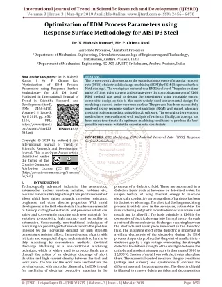
Particulate Whiskers Long Fibers The Material is Al-MMC • Metal matrix composites consist of a metal or alloy as the matrix and the reinforcement (particulate, whiskers and long fibers). • Particulate MMC can be conventionally processed (casting), then secondary processing such as forging, extrusion and rolling can be used • MMCs are very attractive to aerospace and automotive applications (↓density, ↑strength, dim. stable at ↑Temp. • Formed products normally have better mechanical properties than their casted or machined counter parts. For example, the Boeing 747 has about 18,600 forgings (Acharjee, 2006) • Research on metal matrix composites is still very limited (Sapuan and Mujtaba, 2010).
FE Analysis and Optimization • Finite element modeling can greatly reduce testing • and time during product design • FEA steps • Creating model Geometry. • Define Material Properties. • Generate Mesh. • Apply Loads. • Obtain Solution. • Present the Results. • What if we want to check another dimensions (DV) to reduce the strain or stress (SV)? • Do we repeat the FEA steps every time we want to check (DV) • Here we need to use Optimization in conjunction with FEA to really save time
Optimization • Terms • 1- Design Variables. • usually geometric parameters such as thickness, angle, radius etc that will be varied during the optimization process. • min < thickness (t)< max • 2- State Variables. • usually represent some design response and offer a means of limiting the design such as (stress, strain, laps, necking) • Strain (ε) < % of fractural strain • 3- Objective Function. • A state variable to be minimized. (for maximization 1/x) • State variable that represents the (1/tanθ) has been found and then minimized • Design Variable can not be defined as Objective function • To do conduct optimization on ANSYS we need to use APDL
ANSYS Parametric Design Language Copy and past the following lines in ANSYS command prompt. !*create, Analysis File Name /TITLE,sheet metal forming /PREP7 *AFUN,DEG FRICTION=.1 THETA=80!Change to 40 and note the change x1=.06 x3=.03 offs=.04 R1=offs/sin(THETA) x2=R1*cos(THETA) t=.006 radius=.005 K,1,0,0,0, ! Key Points k,2,x1,0,0, k,3,x1+x2,offs,0, k,4,x1+x2+x3,offs,0, k,5,x1+x2+x3,(2*offs)+t+.00001,0, k,6,x1+x2-(t*tan(THETA/2)),(2*offs)+t+.00001,0, k,7,x1-(t*tan(THETA/2)),offs+t+.00001,0, k,8,0,offs+t+.00001,0, k,9,0,offs+.000005,0, k,10,x1+x2+(X3),offs+.000005,0 k,11,x1+x2+(X3),(t+offs+.000005),0 k,12,0,t+offs+.000005,0, K,13,x1+(.4*x2)+.001,offs+.000005,0 K,14,x1+(.6*x2)+.004,offs+.000005,0 K,15,x1+(.4*x2)+.001,(t+offs+.000005),0 K,16,x1+(.6*x2)+.004,(t+offs+.000005),0 LSTR, 2, 1 ! Lines LSTR, 3, 2 LSTR, 4, 3 LSTR, 6, 5 LSTR, 7, 6 LSTR, 8, 7 LSTR, 9, 13 LSTR, 13, 14 LSTR, 14, 10 LSTR, 10, 11 LSTR, 11, 16 LSTR, 16, 15 LSTR, 15, 12 LSTR, 12, 09 LSTR, 16, 14 LSTR, 13, 15 LFILLT,2,1,radius+(t/2), , ! Fillets Radii LFILLT,3,2,radius-(t/2), , LFILLT,5,4,radius+(t/2), , LFILLT,6,5,radius-(t/2), , • APDL is a scripting language which can be used to automate common tasks or even build a model in terms of parameters (variables). • windows APDL editor (http://www.apdl.de/cats/downloads/syntaxeditor_v1_7.zip) • Building the model parametrically will allow ANSYS optimizer vary theses parameters during the optimization process.
ANSYS Parametric Design Language /POST1 *GET, react, NODE, 1, rf,fy, , FoForce=-react PLNSOL, S, EQV, 0, 1, *GET, eqvsts, PLNSOL, 0, MAX, , , PLNSOL, eptt, EQV, 0, 1, *GET, eqvstn, PLNSOL, 0, MAX, , , PLNSOL,CONT,GAP,0,1.0 *GET,gap1,PLNSOL,0,Min, , , congap=-gap1 *get,k14y,kp,14,loc,y,, *get,k14x,kp,14,loc,x,, *get,k13y,kp,13,loc,y,, *get,k13x,kp,13,loc,x,, *get,n14y,Node,10,u,y,, *get,n14x,node,10,u,x,, *get,n13y,node,9,u,y,, *get,n13x,node,9,u,x,, slop=((k14x+n14x)-(k13x+n13x))/((k14y+n14y)-(k13y+n13y)) finish *end *use,Analysis File Name /OPT opanl, Analysis File Name OPVAR,THETA,DV,45,80,, OPVAR,t,DV,.003,.006,, OPVAR,radius,DV,.005,.02,, OPVAR,EQVSTN,SV, ,.75, , OPVAR,congap,SV, ,0.1*t, , OPVAR,slop,OBJ,,,, OPTYPE,SUBP OPSUBP,30,7, OPEQN,0,0,0,0,0, OPEXE finish • APDL enables the user to read many results after processing (/POST1) and defined these results as (SVs) to limit the design space. • This will help ANSYS optimizer refine the optimization search and omits the Infeasible results. • Such as: • A design set with high strain (higher than the fracture strain ε = 0.75 ) • Or with large contact gap 0.05t(sever necking more than)
Results • The optimizer runs the analysis file 8 times (8 iterations). Four sets are infeasible and 3 sets are feasible. the optimal design set is one of the feasible design sets with maximum angle which is set no 8.
Results Infeasible Set The optimal Set FEA and optimization techniques are used in metal forming simulation to reduce the need for testing and experiments and to save time in order to achieve the optimal design
Thank You Mohamed Jolgaf jolgaf@gmail.com http://www.jolgaf.com