Download
1 / 16
160 likes | 339 Views
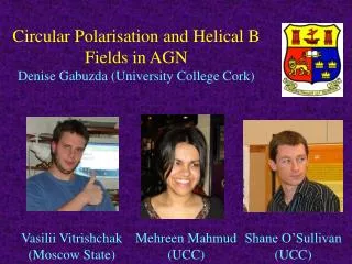
Circular Polarisation and Helical B Fields in AGN Denise Gabuzda (University College Cork). Vasilii Vitrishchak (Moscow State). Mehreen Mahmud (UCC). Shane O’Sullivan (UCC).

E N D
Circular Polarisation and Helical B Fields in AGNDenise Gabuzda (University College Cork) Vasilii Vitrishchak (Moscow State) Mehreen Mahmud (UCC) Shane O’Sullivan (UCC)
Circular polarisation(CP) of synchrotron radiation – very low (less than 0.1%) for B fields thought to be typical (~100G) • First measurements on parsec scales– Homan & Wardle (1999); Homan, Attridge & Wardle (2001) MOJAVE* CP Measurements (Homan & Lister 2006) – 34 of 133 objects had detectable CP at 15 GHz (2 cm), mostly levels of few tenths of a %, mostly in VLBI core – Homan & Lister (2006) searched for correlations between degree of CP and more than 20 parameters – virtually no evidence for any correlations *(MOJAVE – Monitoring of Jets in AGN with VLBA Experiments)
Prime suspect for mechanism generating CP: Faraday conversion of LP to CP when EM wave travels through magnetised plasma. Charges can move only along B in conversion region: component of polarisation E field parallel to B is absorbed & re-emitted by free charges, but component perpendicular to B is not delay of “E parallel” relative to “E perpendicular” Manifest as introduction of small amount of CP
Angle between plane of LP (E) and conversion B field determines sign of CP produced. If optically thin background region with field Bgen emits synchrotron radiation with E Bgen, and foreground region with field Bconv converts some of incident LP to CP, can formulate problem in terms of angle between Bgen and Bconv:
Bconv along +x direction, E Bgen Angle between B fields relative phase between two E field components direction of rotation of tip of E vector sign of CP CCW = – CP
It is essentially the angle between Bgen and Bconv that determines the sign of the CP: 0 < < 90 – 90 < < 180 + 180 < < 270 – 270 < < 360 + Helical B-field geometry can facilitate conversion – LP emitted at “back” of helix is converted to CP as it passes through “front” of helix.
Angle between background and foreground B fields is determined by (1) pitch angle and (2) helicity of the helical field. For pitch angle (angle between axis and direction of B): 0 < < 45 – CP for right-handed helix (0 < < 90) + CP for left-handed helix (270 < < 360) 45 < < 90 + CP for right-handed helix (90 < < 180) – CP for left-handed helix (180 < < 270)
If we can determine rough pitch angle and helicity for jets believed to have helical fields, can predict sign of CP – and in certain cases, we can: • Pitch angle – from observed LP structure (small pitch angle dominant B field along jet, large pitch angle dominant B field orthogonal to jet) • Helicity – from Faraday-rotation gradient across jet
Faraday rotation – rotation of the observed plane of LP when polarised EM wave passes through a magnetised plasma, due to different propagation velocities of the RCP and LCP components of the EM wave in the plasma. The amount of rotation is proportional to the square of the observing wavelength, and the sign of the rotation is determined by the direction of the line of sight B field: • = o + RM 2 RM = (constants) ne B•dl
If jet has a helical B field, observe Faraday-rotation gradient across the jet – due to systematically changing line-of-sight component of B field across the jet. LOS B away from observer B Jet axis LOS B towards observer This is a LH helix. Ο • E
Of the 36 AGN with detected parsec-scale CP at 2 cm (Homan & Wardle 1999, Homan & Lister 2006, Vitrishchak & Gabuzda 2007), we have identified 8 with Faraday-rotation gradients across their jets (Asada et al. 2002; Taylor 1998, 2000; Zavala & Taylor 2003; Gabuzda et al. 2007) and reasonably clear linear polarisation structure: Observed linear polarisation structure pitch-angle regime Direction of Faraday-rotation gradient helicity.
Right-handed helical B field 2251+158 B Zavala & Taylor 2003 Lister & Homan 2005 FR gradient across jet “Spine+sheath” () B field
Left-handed helical B field 0735+178 Gabuzda et al. (2007) FR gradient across jet Predominantly B field
Predictions are correct in 8 of 8 cases! Probability of this happening by “luck” is ~ 0.4% (according to binomial probability distribution).
Homan & Lister 2005 Additional evidence helical B fields are involved: CP detected in jets of several sources! This is very natural if the CP is associated with helical jet B fields.
Summary • We have found firm new evidence that the circular polarisation of AGN is generated by Faraday conversion of linear to circular polarisation in helical B fields associated with the relativistic jets of these objects. • This represents the first direct observational evidence favouring some particular mechanism/scenario for the generation of CP in AGN. • This result also implies that helical B fields may be very common (ubiquitous?) in AGN jets, consistent with the hypothesis that they are generated by the combination of rotation of the central black hole/accretion disk + the jet outflow.