Download
1 / 34
350 likes | 653 Views
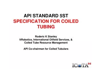
API STANDARD 5ST SPECIFICATION FOR COILED TUBING Roderic K Stanley ItRobotics, International Oilfield Services, & Coiled Tube Resource Management API Co-chairman for Coiled Tubulars. API Tubular Committee Structure.

E N D
API STANDARD 5STSPECIFICATION FOR COILED TUBINGRoderic K StanleyItRobotics, International Oilfield Services, & Coiled Tube Resource ManagementAPI Co-chairman for Coiled Tubulars
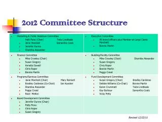
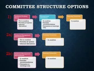
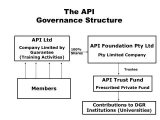
API Tubular Committee Structure • Coiled Tubulars reports upwards to the TGOCTG (for RP 5C7, RP 5C8, Spec 5ST) or TGLP (for Spec 5LCP). • Co-chm now vote on MAG, TGOCTG & TGLP. • We sit on Sub-committee 5 Steering committee.
MINIMUM CHEMICAL REQUIREMENTS 1. Chemical Analysis to cover Cr, Mo, Cu, Nb, V, Ni, Ti, B & other elements added for other than de-oxidation, and these are to be reported. 2. Two rechecks are permitted. 3. Master-coils can be rejected if they fail this analysis
API SPECIFICATION 5ST • Spec 5ST Took 12 years to get into print. • Grades CT70, CT80, CT90, CT100, CT110. • Sizes 0.750 - 3.500-in. • Does not contain information about (a) use in sour service or (b) fatigue models/life. • (These would be better suited to recommended practices) 5LCP & 5ST are MANUFACTURING documents, and contain no information about service-related problems.
5 ST DOCUMENT LAYOUT Annexes A – Tables (Normative). B - Tube-to-tube Welding (Normative). C – Skelp-End & Tube-Tube Procedure Specifications (Normative). D - Supplementary Requirements (Normative). E - Purchaser Inspection (Normative). F - Use of Monograph by API Licencees (Informative). G – Shipping/Service reels (Informative). H - SI Conversions (Normative). 1. Scope 2. References 3. Definitions 4. Information to be Supplied by the Purchaser • Mandatory • Optional 5. Processes of manufacture 6. Material requirements 7. Dimensions, masses/Unit Length, Defects, End Finishes. 8. Testing 9. Test methods 10. Nondestructive Inspection 11. Invalidation of tests 12. Retests 13. Marking 14. Coating and Protection 15. Document Control & Retention 16. Certification.
5ST PAPERWORK REQUIREMENTS -1 Optional/Agreement Requirements 1. Additional NDE of SE & Butt welds. 2. Alternate NDE reference indicators (notches, IQIs). 3. Demonstrations of NDE reference standards. 4. Final string length profile. 5. Additional hardness tests. 6. Impact tests. 7. Minimum acceptable remaining wall. 8. Whether internal flash is to be removed. 9. Alternate hydrotest pressure and time. 10. A measurement of ovality [ = 200 (Dmax - Dmin)/ (Dmax +Dmin)]. 11. Grain size measurement. 12. Internal and external coatings. 13. Markings in SI units. 14. Documentation to be provided to the customer. 14. Actual chemical composition. • Mandatory Purchasers Requirements • Grade • Method for YS (0.2% offset or 0.5% extn UL). • Length, diameter, wall thickness(s) • End fitting. • Product analysis. • Drying procedure. • Drift Ball material (e.g. carbon steel). • NDE Reference indicators for all NDE. • Retests (within 50-ft or original test). • Final (SR 37) NDE. • Shipping reels & delivery data.
PAPERWORK REQUIREMENTS-2 String Design • The purchaser and the mill should design a string before manufacturing begins. The final design often depends on the material in stock, and where skelp-end welds need to be located with regard to working them over the guide-arch. • Final design to be agreed. • Regard should be paid to reel size and weight, and to transportation.
WALL THICKNESS CHANGES BETWEEN SKELPS Alternatively, one mill uses continuous tapering within strips, with no thickness change at the ends.
SKELP TESTS • Skelp: Skelp should be inspected for scabs, pits, laminations, etc., as a purchasing quality requirement, but neither 5ST nor 5LCP specify this. This is because the skelp is assumed to be compliant with the CT mill’s requirements. • Skelp-End Welds: These must be manufactured to written procedures, which should include NDE. • Friction-stir welding is included. • The finished SE welds must be flush with the wall surfaces. • Radiography(RT) is mandated for CT and CLP. (As a minimum, an ASTM 2T hole, or specified wire image quality indicator is used. The sensitivity may be modified by agreement). • Ultrasonic Shear wave (UTSW) is a customer call, with its notch reference indicators specified in 5ST. • Surface hardness tests must also be conducted and be in compliance with the table.
BUTT WELDS • Butt Welds: Customers determine whether a butt weld is permitted. In many strings, they are not a problem. • External weld crown flash must be removed so that there is not more than 1/32-in. excess. • They must be made to a written procedure and NDE-testedat least byRT. • The customer can require additional UT. (In some situations, we require UTSW after a weld has passed RT, because of RT’s inability to find 2-dimensional defects). • Surface hardness tests must be conducted at the weld, the HAZ and the parent metal.
TENSILE TESTING REQUIREMENTS 1. Taken at ends and at “mill stops”. Add “mill stop” results in if (2) is used. 2. Can use prior results from sale heat, size, grade, heat treatment. 3. Two retests possible. If end tests fail, take 2 more within 50-ft.
FLARING REQUIREMENTS • To ASTM 450 at each end of continuously milled lengths, mill stops. • Flare over 60 deg mandrel • CT90 & below IDf = 1.25 x ID. • CT100 & higher IDf = 1.21 x D. • Retests: 2 additional tests • One more within 50-ft.
IMPACT TESTS Impact Tests (32F/0C): Where size permits, impact tests and retests can be called out by the customer. Minimum requirements are (table 5): Retests: Two sets of retests are permitted within the 50-ft rule above. We are aware of impact tests being performed regularly on bias welds, seam welds, butt welds, and in the body of the material from low to high temperatures and after strain aging for CLP, but only rarely for CT.
THE SEAM WELD VISUAL • Metallurgical Examination: Specimens are to be ground, polished and etched so that the microstructure can be viewed. In the case of “flash-in” tubing, the weld root shall show that it is continuous with smooth curves blending into the inside diameter of the tubing.
HARDNESS/MICROHARDNESS TESTS Skelp-End Welds and Butt Welds: The minimum requirement is for external surface measurements on each weld, HAZ & strip. • Scans through welds must be performed as part of the welding procedure qualifications. (done with a micro-hardness tester). • Customer can request more readings.
MICROHARDNESS AT SEAM WELD Seam Welds: Using material taken next to the tensile test material, standard microhardness tests are taken close to the in the seam weld, the HAZ and the parent tube wall close to the ID, midwall, and close to OD(9 readings in all). The customer can request more readings. All readings must be within the limits of the table. • Retests: One set of retests is permitted. If high readings occur, the strip from which the tube is made is rejected.
THE HYDROSTATIC TEST • This is mandated to be a minimum of 1.6Syt/D for 15 min. at constant pressure for the thinnest section of a string. • Customers can require higher pressures or longer times at pressure. • Recall that a mill hydrotest is a proof test of the seam weld on the reel. • What people do in field use is their own problem.
IN-LINE NDT • The tube is assessed in-line by electro-magnetic or ultrasonic methods. Reference standards shall contain longitudinal 10% deep notches [minimum depth 0.015-in. (0.38 mm)] and drilled holes [(1/32-nd in. (0.8 mm) or 1/16th –in. (1.6 mm)] that can be partially or entirely through the wall.So the customer and the manufacturer must agree on the reference indicator(s) during contract review. • The customer may require to observe the set up tests.
OFF-LINE NDE (SR 37) • 5ST allows the customer to call for an off- • line re-inspection after the hydrotest SR37). • The reference standards for the equipment are OD and ID (where possible) EDM notches of length 0.500 (LID, LOD), 0.250-in. (TID, TOD), depth 10% of specified wall (thick end), minimum depth 0.015-in, maximum width 0.020-in., and a 1/32nd in. through drilled hole (TDH). • These reference indicators must be detected clearly in 4 quadrants before and after the string is inspected. • Inspection personnel MUST be suitably qualified and certified. • This inspection is being called out more and more for strings that are destined for Europe, for offshore Newfoundland and the GoM. • Chafing marks from the sides of the reel, and internal spume are being found.
WALL TOLERANCES These are for unrepaired areas of the tubing wall
OVALITY The tolerance is 0.010-in. from specified diameter (D), which is generally measured at the ends of the tubing. The customer can call for additional ovality measurements. Ovalityis also measured after OD flaw removal as part of a SR 37 inspection.
NOT good! NOT good! OD SURFACE FLAW REPAIR • The OD surface can be repaired by removing chafing marks, gouges, etc, and finishing with 400-600 grit-size sandpaper. • It is recommended that not more than 10% of the specified wall thickness is removed. This often occurs during the SR 37 inspection. Length or removal should be at least 2 x diameter of tube
DRIFTING THE TUBING • Drift ball sizes are given in 5ST, the ball material (nylon, steel, other) being specified. • Wiper and drift balls often help to clean out spume, and assure a minimum ID. • For “flash-in” tubing, the flash column at the seam shall not be more than 0.090-in. (2.3 mm) from the original inside surface.
MARKING • CT that meets all requirements shall be marked (a) on the reel and (b) durably on a tag with the following: • Manufacturer, Spool number, “Spec 5ST,” (Comparable standard), OD, Grade (e.g. CT80), Tested xxxxx psi, NDE SR37 (if performed). • The length shall be paint-stencilled on the reel.
COATINGS & PROTECTION • Unless otherwise specified, CT shall be given a protective coating. The purchase agreement shall state if special coatings are required. • Uncoated tubing shall be protected from water ingress by placing them under cover. • By agreement, the tube shall be filled with a dry non-reactive gas, and the ends sealed. • By agreement, the internal surface shall be protected with a corrosion inhibitor approved by the customer.
DOCUMENTATION • At least the following documents shall be kept by the mfrfor each string. • When specified by the customer, the following shall be supplied. • A certificate stating the API Spec and revision date. • Diameter, wall thickness(es) and grade. • Chemical analysis (heat, product if required) showing mass per-cents as elucidated in 5ST. • Tensile and hardness test data. • All weld locations, measured from reference end. • Test pressure and duration at pressure. • Inline NDT method, & reference indicators. • Type/size of all IQIs & other reference standards. • Fracture toughness tests (type, sample size, orientation, location), if applicable. • Results of supplementary tests required by purchaser. • Spool size and # of times spooled. • Certification of drying procedure. The spool documentation above shall be kept for at least 5 years, long with tester charts, radiographs and other NDE data, and NDE personnel qualification and certifications.
TYPICAL FLAWS FOUND IN SR37 • OD chafing marks found in new tubing MFL signal from on of the flaws
MAGNETIC PARTICLE & LIQUID PENETRANT • MT and PT are to be used to investigate indications found during in- or off-line NDE, such as might originate from open/partial/incomplete/intermittent welds, cracks, seams, overlaps, and slivers. • These are then explored for depth, and may be fully removed. • Customer sets requirements for remaining wall thickness after flaw as are repaired at mill.
API DOCUMENT CHANGES • The need for coiled tubing standards was noted in 1992. • API decided that it was too early to write a “Specification”, but approved the writing of a recommended practice. • API RP 5C7 was the first “catch-all” (manufacturing, usage, corrosion, collapse) document published in 1996, & wasreaffirmed by API RGCT twice. • Now to be withdrawn as all text has been taken into 5ST, RP 16ST, RP 5C8. • API RP 16ST published in 2009 to cover certain aspects of field use.
SUMMARY • You now have a national manufacturing STANDARD from which you can order CT. • We document what exists today, and added some items. • Grades outside of those listed are not API grades. • Some restrictions occur for on lower grades. • A re-inspection after the hydrotest has been added, and appears to be used for critical strings. • The document will be reviewed by the RG for CT in 5 years. • Publication of this document, along with RP 16ST and eventually RP 5C8 will allow RP 5C7 to be withdrawn.