Download

1 / 25
250 likes | 416 Views
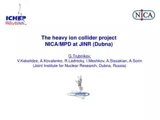
Time-Projection-Chamber for MPD NICA Project. Stepan Vereschagin On behalf of the TPC team: A.Averyanov , A.Bajajin , V.Chepurnov , S.Chernenko , G.Cheremukhina , O.Fateev , A.Korotkova , F.Levchanovskiy , J.Lukstins , S.Razin , A.Rybakov , S.Vereschagin , Yu.Zanevsky ,

E N D
Time-Projection-Chamber for MPD NICA Project StepanVereschagin On behalf of the TPC team: A.Averyanov, A.Bajajin, V.Chepurnov, S.Chernenko, G.Cheremukhina, O.Fateev, A.Korotkova, F.Levchanovskiy, J.Lukstins, S.Razin, A.Rybakov, S.Vereschagin, Yu.Zanevsky, S.Zaporozhets, V.Zruyev TPC/MPD Collaboration Laboratory of High Energy Physics, JINR, Dubna Novosibirsk, 2014
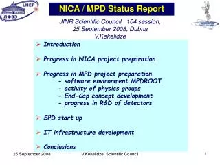
CONTENS • TPC design overview • Field cage and central cathode plane • TPC readout chamber (ROC) • Front-End electronics (FEE) • TPC laser calibration • Gas system • Cooling system • Conclusion
General view of the MultiPurposeDetector (MPD) NICA project • SC Coil - superconductor solenoid • IT - inner detector • ECT - straw-tube tracker • TPC - time-projection chamber • TOF - time-of-flight stop counters • FD - The fast forward detectors • ZDC - zero degree calorimeter • BBC - beam-beam counter
TPC design overview beam 12x2 Readout chambers E beam HV-electrode Field cage Physics requirements: • The overall acceptance on │η│~ 1.2 • The momentum resolution ~ 3% in pt interval from 0.1 to 1 GeV/c Two-track resolution ~ 1 cm. Charged particle multiplicity ~ 1000 in a central collisions • Hadron and lepton identification by dE/dx measurements with resolution better than 8%
The front view of the TPC Four cylinders (green circles: C1 - C4) are required to make the complete field-cage structure. All four TPC cylinders are under construction in Russian Industry as monolithic Kevlar composite constructions. Kevlar thickness is 4 mm. Such an approach allows one to minimize problems with gluing of field cage parts and fragments. Moreover, we suppose to mount field cages, central electrode and end plates as independent precisely adjusted constructions which will be inserted between Kevlar сylinders and fixed together mechanically and with epoxy.
Construction of TPC cylinders • Material : Kevlar • Thickness: 4 mm • Length: 3.4 m • Diameter: 2.8 m • Deformation in operational position is less than 100 mkm
Field cage and central cathode plane TPC prototype field cage TPC prototype under constraction
Field cage The non uniformity of the electric field inside the sensitive TPC volume has to be not more than 10-4 relative to nominal value (140V/cm P10 gas mixture) The field distortions in the drift volume defined by mylar strip system a) precisely placed strips b) one strip is shifted by 50μm The distortions are down to 10-4 at ~23mm from the strip surface inward drift space. The positioning precision of the strips into nominal place has to be not worst than 50μm. The dependence of the size of the worst region with the field distortion more than 10-4 ✔Along the line parallel the strip surface(orange line) ✔Inward the drift space (violet line)
Readout chamber Structure of readout chamber: - three wire planes - pad plane - insulation plate - trapezoidal aluminum frame • Pad structure • pad raw number 53 • rectangle shape • - small pads 5×12 mm2 • - large pads 5×18 mm2 Wires structure - anode wire pitch 3 mm - cathode wire pitch 1,5 mm - gate wire pitch 1 mm - wires gap 3 mm Padplane Insulationplate Al-body
TPC readout chamber: Al body • The aluminum frame provides the overall mechanical stability of the readout chamber. Its stability against deformation caused by wire stretching has to provide as minimal as possible overall deformation less than the expected wire sag caused by electrostatic forces. • The frame is reinforced by stiffening rib • The deformations do not exceed 27 mkm at the total wire tension ~ 800 N and over pressure inside TPC up to 5 mBar Finite element calculation of the deformation of the readout chamber caused by the wire tension and over pressure inside TPC
Front-End Electronics • Signal to noise ratio, S/N - 30 • NOISE < 1000e-(С=10-20 pF) • Dynamic Range - 1000 • Zero suppression • Buffer (4 / 8 events) PASA ALTRO ALTERA FPGA ALTRO PASA Front-End Electronics prototype (USB2.0) Microsemi FPGA 3d-model of the new Front-End Electronics
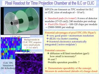
TPC testing Generalviewofthelaser beamsinside TPC. UV lasertracksreconstructedinPrototype1. Prototype 1 underpreparing totestwith UV laser.
TPC Laser Calibration System Inordertominimizetheerrorintheabsolutepositionmeasurementby TPC, itisnecessarytotakeintoaccountbothstaticandtime-dependentdistortionsinthedriftpathoftheionizationcloud. A calibration system that can reproduce fiducial tracks is needed to monitor the TPC performance. This calibration system will be based on the UV laser. Semitransparent mirror Mirrorsreflect beamat 900 LaserNL313-10 Thereare 224 laserbeamswhole TPCin Schemeofhighpowerlaserbeamsplittinginto 112 “tracks” of 1 mmdiameter.
TPC gas system Vent Insulating gap Ar Insulating gas Requirements 90%Ar+10%CH4 The drift volume is 18500 liters, the insulating gaps – 4800 liters Hermetically closed-loop gas circulation system Dryer and purification in return line Continuous monitoring of gas gain and drift velocity – gas chromatograph Gas mixture temperature control - 0.5 K Internal TPC pressure – 2 mbar Recirculation flow - 3.8 m3 /h CH 4 Exhaust system CO Mixer 2 Gas supply N 2 TPC Gas quality monitor Drift volume Absorber Purifier Compressor 2 CO Buffer Schematic view of the TPC gas system structure
TPC Cooling SchemePreliminary estimation Front End Cards cooling Resistor rods cooling Outer thermal screen inner thermal screen TPC gas volume, ∆T<0.50C Cover cooling Bus bar cooling FEE/ROC dissipation < 400 W Resistor rods 2 x 8 W Bus bar < 500 W
TPC TPC cooling system Flow rate: • FEEC: 24 x 1m3/h • ROC Covers: 24 x 0.2 m3/h • Thermal screen: 24 x 0.5 m3/h Total flow: 40 m3/h Total heat to be removed: up to 10kW Total Volume of water in the installation: 600L Installed Electrical Power: • Pump: 11kVA • Heaters: 26kVA Total Power: 37kVA Number of Circuits: • FEEC: 12+12 • ROC Covers: 2+2 • Therm screen: 12+6 • Resistor rods: 2+4 Total: 52 Temperature Sensors Reservoir Shut off valve Heater Heat Exchanger at Exchanger Circulator Pump pressure in cooling loops is kept below atmospheric pressure
Temperature Monitoring Sensors: blue – on the field cage, red on the chambers
Conclusion • Design of main parts of TPC are performed. • Three of fours TPC cylinders are constructed. • Technological Prototype TPC was designed, constructed and tested with laser beam and cosmic. • Readout Chamber (RoC) is designed and full size prototype is under construction. • The prototypes of FEE are constructed and tested. • Software is under developing. • Laser calibration system is designed. • Gas and Cooling systems are under designing.
Thank you for attention! and welcome to collaboration.
ENERGY LOSS He3 He4 H3 D P P K π e TPC FEE input full scale amplifier ~ 200 fC It is ~ 30-40 MIP energy loss The energy loss distribution in the MPD TPC PID:Ionization loss (dE/dx) Separation: e/h – 1.3..3 GeV/c π/K – 0.1..0.6 GeV/c K/p – 0.1..1.2 GeV/c QGSM Au+Au central collision 9 GeV, b=1fm
ALICE TPC FEE FEC in Cu sandwich 6 cables per FEC 128 ch/FEC