Download
1 / 41
410 likes | 602 Views
A Time Projection Chamber for the International Linear Collider. Thorsten Lux University of Hamburg/ DESY. Outline. Basics of a Time Projection Chamber The ILC Project TPC R&D Summary. Time Projection Chamber. Gas Volume. Readout Plane. B, E field. inner Field Cage.

E N D
A Time Projection Chamber for the International Linear Collider Thorsten Lux University of Hamburg/ DESY
Outline • Basics of a Time Projection Chamber • The ILC Project • TPC R&D • Summary Thorsten Lux
Time Projection Chamber Gas Volume Readout Plane B, E field inner Field Cage outer Field Cage Amplification Device Cathode Thorsten Lux
Working Principle cathode anode Thorsten Lux
~ ~ mm + G Why a TPC? • low material budget • a large number of 3D space points • E, B parallel no E x B effects • detection of long living particles • cheap • good dE/dx measurement capability • established detector Thorsten Lux
Choice of the Gas • in principle: every gas with low attachment coefficient and stable gas amplification • normally: noble gas + quencher gas ( e.g. CO2, CH4) Some Basic Rules: • total number of primary e- large • vd(Ed) large maximum at small Ed,max • DL small, DT “optimal” (depends e.g. on B field) • gas properties only slightly affected by impurities + changes in temperature and pressure • safety ( preferable not flammable), no ageing effects Thorsten Lux
There is no the one and only TPC GAS! Influence of gas impurities Thorsten Lux
Field Cage The field cage should ... 1) provide a highly uniform E field 2) protect the gas against impurities + do not pollute the gas by itself 3) electrically and mechanically stable This all with as less material as possible! ( to avoid multiple scattering in front of calorimeter) Several options for each of these points, as you will see in the following: Thorsten Lux
Field Uniformity Aim:electric field of an infinite parallel-plate capacitor ideal solution: covering the walls with material with high resistivity real solution : covering the walls with equally spaced conducting strips connected via identical resistors Thorsten Lux
Field Strip Design Danger of charging up the insulator between strips Distortion of the electrical field Solutions: • mirror strips on the back of the insulator • retracted strips: height >> gap Thorsten Lux
Field Cage Design The walls of the field cage have to ... 1) withstand the high voltage close to the cathode ( 50-100 kV) 2) not to deform under their own weight They should ... 3) have in total a material budget of only a few percent of X0 Thorsten Lux
‘ALEPH’ type : • solid • sandwich structure • strips coated on walls • higher danger of permanent damage • ‘ALICE’ type : • separation of field uniformity and insulation • strips separated from walls • gas insulation • large dead regions • field uniformity? Thorsten Lux
Gas Amplification Devices • Wire readout (classically used) • Gas Electron Multiplier (GEM) • Micromegas } ongoing R&D Wire Readout good reasons to look for alternatives: • E x B effects • ions might drift back to gas volume • wire under tension requires a lot of material • slow ion signal Thorsten Lux
primary charges ions electrons amplification region GEMs • introduced by F. Sauli (1996) • 50 m thick kapton • coated with 5 m layers of copper • highly perforated (140 m pitch, 70 m hole diameter) • voltage of several hundred volts applied between copper layers • amplification within the holes • gain up to 104 for a single GEM feasible • higher stability (at high gain) with Multi-GEM-Structure + more flexibility (ion feedback) Thorsten Lux
Amplification gap: 50-100 m Readout plane Spacer Micromegas Y. Giomataris et al. (1996) Thorsten Lux
Pro and Contra of MPGDs Pro: • intrinsic ion feedback suppression • amplification structures in order of ~100 m • fast electron signal Contra: • higher risk of permanent damage due to sparks • toonarrow signal • • no centre-of-gravity Thorsten Lux
Design of the Readout Plane Possible solutions for the narrow signal problem: 1) smaller pads ( limited by total no. of channels/ costs) extreme case: pixel readout/ Digital TPC 2) capacitive or resistive coupling of adjacent pads 3) charge spread close to the pads 4) alternative pad geometries 5) alternative reconstruction methods Rectangular Chevrons Staggered Thorsten Lux
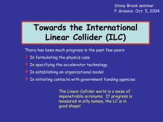
ILC Project • e+e- Linear Collider • centre-of-mass energy : ~90–1000 GeV (corresponding to length of 30-40 km) • luminosity 1034 cm-2s-1 • will be based on superconducting cavities • complementary to LHC • polarised beams • several other running options: , e, e-e- TESLA design Thorsten Lux
Milestones 1990s : 3 studies (TESLA, NLC, JLC) 2004 : Recommendation of the ITRP sc technology 2005 : Conceptual Design Report 2007 : Technical Design Report 2008 : Site Selection 2009 : Construction could start 2015 : First beams possible Thorsten Lux
Reasons for a Linear Collider Notice: A linear collider will be put into operation after major LHC discoveries Why is an e+e- linear collider still needed? • Clean • well defined initial state • electro-weakly interacting initial state • tiny beam spot good flavour tagging • Flexible • tuneable beam energy e.g. threshold scans • polarised beams • different running options • Precise • precise theory predictions • excellent detector resolution ( main focus on physics, not on radiation hardness) • precisely known, high luminosity Thorsten Lux
Road to Exploration Thorsten Lux
Must also be able to cope with high track densities due to high boost and/or final states with 6+ jets, therefore require: • high granularity • good pattern recognition • good two track resolution Physics Requirements on the Detector Momentum: 1/p < 7x10⁻⁵/GeV(1/10 x LEP) ( e.g. Z mass reconstruction from charged leptons) Impact parameter: d0 < 5mm5mm/p(GeV)(1/3 x SLD) (c/b-tagging in background rejection/signal selection) Jet energy : dE/E = 0.3/(E(GeV))1/2(1/2 x LEP) (W/Z invariant mass reconstruction from jets) Hermetic down to : q = 5 mrad (for missing energy signatures e.g. SUSY) 3 different approaches: SiD, Large and Huge detector concept Thorsten Lux
Large Detector Concept • SC Solenoid withB ~ 4 T • high granularityHCAL (inside coil favoured) • high granularityECAL (SiW generally favoured) • large gaseous central tracker(TPC) • precision microvertex detector(first layer close to IP) Main Focus on Precision! TESLA design Thorsten Lux
A TPC for the ILC How could a TPC for the ILC look like? • TESLA example: • length: 5.46 m • diameter: 3.4 m • magnetic field 4 T • 1.2 x 10⁶ channels • 200 space points per track • Desired precision: • p/p2 = 1.5 x 10⁻⁴ GeV-1 • dE/dx accuracy: 5 % • single point resolution: 140 m Thorsten Lux
TPC R&D for the ILC • really a international project: 20 institutes from 8 countries • not only research in parallel but really together • investigating very different aspects with various setups Thorsten Lux
Optimisation of GEM Settings What are the optimal settings to get the minimal ion feedback? RWTH Aachen What is acceptable? Save side: Thorsten Lux
Micromegas Properties Orsay/Saclay Similar studies are ongoing for Micromegas Thorsten Lux
Hamburg Tested setup with both: GEMs and Fe55 source and ... Micromegas and cosmic muons 14 mm and a classical electron candidate 14 mm Digital TPC Pixel readout with 55x55 m2 pixels NIKHEF Thorsten Lux
Resistive Foils with Micromegas and x-ray Carleton/Orsay/Saclay Thorsten Lux
RWTH Aachen: Uses a modified GEM design to decrease ion feedback (MHSP) CERN Standard GEM Russian GEM • 3M investigated together with institutes from the USA mass production: • low production cost per unit (~ 2 USD/GEM) • 2 different fabrication techniques • ongoing R&D • KEK/Fuchigami started to look into other GEM production processes: • gain seems to be similar to CERN GEM • ongoing studies of stability 50x amplification Different GEM Designs/ Sources Thorsten Lux
Resolution Studies • 5 T Test Facility • superconducting magnet • inner diameter 28 cm • length coil 120 cm DESY further magnets with lower magnetic fields 1-2 T available in Canada, France and Japan Thorsten Lux
0 T 4 T Thorsten Lux
preliminary • Hamburg • Ar:CH4:CO2 93:5:2 • 2.2 x 6.2 mm2 pads • classical fit method ILC preliminary • Victoria group • But ... • smaller pads • different gas • alternative fit method ILC Thorsten Lux
Hamburg Wedge • how well can 2 tracks separated in z and r? • Nd:Yag laser with 266 nm • ongoing studies (later also in the 5 T magnet) Double Track Resolution: Thorsten Lux
Summary I hope, that I convinced you, that ... • TPCs are interesting and exiting detectors • they have a lot of development potential • it is interesting to participate in the ILC • TPC R&D (for the ILC) is an international and promising project Thanks for your attention! Thorsten Lux
mass and width - threshold scan: Physics Motivation • Higgs Boson: precision measurement of the mass; it is really the Higgs? • Supersymmetry: spectroscopy; determine of the “low-energy” parameters • Extra Dimensions: how many dimensions exists? • Precision SM Measurements: mtop, mW Thorsten Lux
time period Track + Particle Reconstruction z-coordinate from drift time z = vdrift · (ts-t0) 1990: primary e- trajectory of the charged particle r-coordinate from segmented pad plane 3 dim. Reconstruction • dE/dx out of charge on pads • momentum from B-field • Particle Identification Thorsten Lux
S1 S2 GEM and Micromegas S1/S2 ~ Eamplif / Edrift Thorsten Lux
Berkley/Orsay/Saclay • pad size 1x10 mm2 • Ar:CF4 97:3 • hard phi cut Thorsten Lux
use informations from all rows at once • maximum-likelihood fit • calculate points row wise • fit through all points Thorsten Lux