Download
1 / 31

E N D
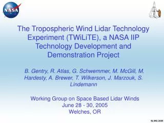
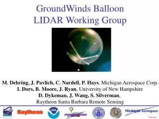
Mid-term status of the TWiLiTE direct detection Doppler lidar development programBruce Gentry1,M. McGill1, G. Schwemmer6, M. Hardesty2, A. Brewer2, T. Wilkerson5, R. Atlas2, M.Sirota3, S. Lindemann4, F. Hovis71NASA GSFC; 2NOAA; 3Sigma Space Corp.; 4Michigan Aerospace Corp.; 5Space Dynamics Lab; 6SESI, 7Fibertek Inc Working Group on Space-Based Lidar Winds July 17-20, 2007 Snowmass, CO
TWiLiTE Overview Requirements and Performance Simulations Instrument Subsystem Status Summary Outline
Technology Maturity Roadmap Past Funding Laser Risk Reduction Program 2-Micron Coherent Doppler Lidar IIP-2004 Projects High Energy Technology 1997 2 micron laser 1988 Diode Pump Technology 1993 Inj. Seeding Technology 1996 Conductive Cooling Techn. 1999 Compact Packaging 2005 Packaged Lidar Ground Demo. 2007 Autonomous Oper. Technol. Pre-Launch Validation Lifetime Validation Space Qualif. Aircraft Operation Operational Demo UAV Operation TWiLiTE Autonomous Oper. Technol. 2008 (Direct) Space Qualif. Pre-Launch Validation Lifetime Validation 1 micron laser Diode Pump Technology Inj. Seeding Technology Conductive Cooling Techn. Compact Laser Packaging 2007 High Energy Laser Technology Compact Molecular Doppler Receiver 2007 0.355-Micron Direct Doppler Lidar
Tropospheric Wind Lidar Technology Experiment (TWiLiTE) Instrument Incubator Program • TWiLiTE will demonstrate, for the first time, downward looking wind profiles from 18 km to the surface obtained with an airborne direct detection scanning Doppler lidar • The TWiLiTE instrument is compact, rugged and designed for autonomous operation on the NASA WB57. • TWiLiTE will be completed in summer 2008. • The instrument could be transitioned to a UAV like Global Hawk . Rotating HOE telescope Doppler Receiver UV Laser TWiLiTE system integrated on WB57 3 foot pallet
Airborne Doppler Lidar Wind Profiling 250 m Lidar ranging permits determination of wind speed as a function of altitude. Multiple look angles permit determination of vector wind.
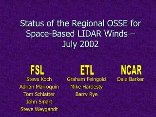
Specification WB57 Max. Altitude 18 km Duration 6.5 hours Cruise Speed 200 m/s @ 18 km Payload mass 374 kg per pallet X 4 pallets. Payload Electrical Power 110V, 4 X 25A, 3 phase, 400 Hz; 28V DC 35A Payload mounting Modular pallet Nadir view TWiLiTE Target Platform WB57 Aircraft: NASA Johnson Space Center 3’ instrument pallet
TWiLiTE Instrument Parameters Wavelength 354.7 nm Telescope/Scanner Area 0.08 m2 Laser Linewidth (FWHH) 150 MHz Laser Energy/Pulse (6 W) 30 mJ @ 200 pps (8 W) 40 mJ @ 200 pps Etalon FSR 16.65 GHz Etalon FWHH 2.84 GHz Edge Channel Separation 6.64 GHz Locking Channel Separation 4.74 GHz Interference filter BW (FWHH) 120 pm PMT Quantum Efficiency 25% Optical Efficiency (Edge w/o BS or etalon) 0.37 BS 0.41
107 black = overlap corrected, no max. count rate blue = overlap corrected, 50 MHz max. count rate 106 detected photons 105 104 0 5 10 15 20 Altitude (km) Photocounts Detected in each Edge Channel 10 sec (2000 shot) integration; z=250 m; 45 deg nadir Includes effects of lidar overlap function and the use of 3 PMTs sharing the incoming signal in the ratio 90:9:1 to increase linear counting dynamic range.
TWILITE system performance Simulated L-O-S wind error 20 Current system performance (red curve) includes telescope with 58% diffraction efficiency and 55% encircled energy. Expected system performance (blue curve) includes telescope with 62% diffraction efficiency and 82% encircled energy. In both cases, the black curve is the performance with no solar background included. 15 Altitude (km) 10 5 red = performance with current system parameters blue = performance with expected system parameters 0 0.0 0.5 1.0 1.5 2.0 L-O-S wind error (m/s)
8 point conical step stare scan pattern Top view Aircraft motion • Scanning parameters: • Constant dwell of 10s/LOS • Fixed azimuth increments of 45 deg in CW steps Radial HLOS wind speed measured in a single range bin for 3 cycles of the 8 point step stare scan pattern. Assumes constant velocity (maximum = 40 m/s)
Steps in etalon resonant frequency are created by vapor deposition of fused silica on one plate. Triple Aperture Step Etalon - Michigan Aerospace Corp Full Field Fringe Pattern
Volume reduced by 90% versus current GLOW receiver Optical path lengths minimized to improve mechanical, thermal stability End-to-end throughput increased by 60% Signal dynamic range increased by 2 orders of magnitude TWiLiTE Receiver Design Summary
TWiLiTE Holographic Telescope FUNCTIONS • Collect and focus laser backscatter • Scan laser and FOV • Provide pointing knowledge to CDH FEATURES • Primary Optic: Rotating 40-cm HOE, 1-m f.l. • 45-deg off-nadir FOV • Compact, folded optical path • Coaxial laser transmission • Active laser bore-sight
Telescope Mechanical Design 3 mount points Envelope Dimensions: 25” Height 30” Diameter (includes mounts and motor, 25” without) Total Mass: 51 kg (112 lb)
Laser Transmitter Specifications Performance Specifications/Design Performance Summary Table
Laser Module Overview • Injection seeded Nd:YAG ring oscillator with single amplifier • Frequency tripled to 355 nm • Pulse energy = 30 mJ @ 355 nm • Pulse Rep Frequency = 200 pps • Optical canister is 28cm x 33 cm Front View Resonance detection photodiode Ring oscillator 1064 & 532 nm output window 355 nm output window Amplifier Compartment Oscillator head Amplifier Purge port Coolant connector Isolator SHG THG Modulator & q-switch drive electronics Seed laser Periscope Oscillator Compartment See Hovis et al, “Advanced Transmitters for Ladar Applications” in Session 11
1 2 3 4 5 TWiLiTE Assembly 1- Floor; 2- Mounting frame; 3- Optical bench (laser &HOE rotating telescope); 4- Receiver & Electronics ; 5- WB57 Pallet Mass: 250 kg Power: 770W (not including heaters)
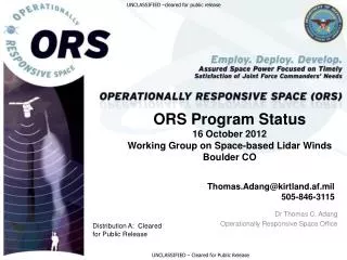
Project Timeline LASER DELIVERY JUL 2007 TELESCOPE DELIVERY AUG 2007 RECEIVER DELIVERY AUG 2007 TELESCOPE SUBSYS PDR MAY 22, 2006 CRITICAL DES REVIEW MAY, 2007 TEST FLIGHTS LATE SUMMER 2008 CONCEPT DES REVIEW FEB 16, 2006 START: AUG 2, 2005 SYSTEM REQ WORKSHOP DEC 1, 2005 PRELIM DES REVIEW JUL 20, 2006 ASSEMBLY INTEG & TEST 3Q/2007- 2Q/2008 FINISH: AUG 1, 2008 RECEIVER SUBSYS PDR (GSFC IR&D) MAR 2005 ETALON DELIVERY APR 2007 2006 2007 2008
TWiLiTE Summary • TWiLiTE is a three year R&D project to design and build an airborne scanning direct detection Doppler lidar • The primary objective is to advance the TRL of key component technologies as a stepping stone to space. • The TWiLiTE Doppler lidar will be serve as a testbed to validate critical technologies in a fully autonomous, integrated Doppler lidar as a stepping stone to space. • The instrument will is designed to measure full profiles of winds from a high altitude aircraft and many of the design elements may be transitioned to UAV or other suborbital platforms for mesoscale and hurricane research. • Acknowledgements: ESTO IIP Program; Goddard Space Flight Center IRAD program
Mission Applications • Global Tropospheric Wind Sounder • Improved NWP • Hurricane and severe storm prediction • Airborne Doppler Lidar • Mesoscale research • Improved hurricane prediction • Satellite cal/val • Technology validation • Exploration • Martian winds from orbit or surface
Doppler Lidar Measurement Concept • MOLECULAR DOPPLER RECEIVER • Molecular return gives lower accuracy and resolution but signal is always there Double-edge filters sample wings of molecular spectrum to measure Doppler shift
In 1999 the first molecular “double edge” Doppler receiver was built as a proof of principle experiment. The molecular receiver was installed in the GLOW mobile Doppler lidar to demonstrate the functionality and scalability of the approach 5 years of ground based lidar wind measurements in a wide variety of conditions. m/s deg Double Edge Doppler Lidar Heritage Receiver mounted in GLOW lidar for field tests and measurements Double-edge filters sample wings of molecular spectrum to measure Doppler shift GLOW mobile Doppler lidar Time series of wind speed and direction profiles from IHOP_2002
HARLIE TWiLiTE GLOW CPL TWiLiTE IIP Overview Objective: Advance TRL of key enabling technologies for direct detection Doppler lidar including validation at the instrument system level from a high altitude aircraft • NASA IIP 2004 • Started: Aug 1, 2005 • 3 year effort • Leverages significant technology investments and instrument development heritage: • IR&D + SBIR + IPO + ESTO • Laser – Fibertek • Data System – Sigma • HOE – Ralcon • FP etalon – MAC • Heritage from Fielded Lidar Systems: • GLOW, CPL, HARLIE ESTO IPO SBIR IR&D
A/D SIGNAL FIBER WATER POWER System Block Diagram Power Dist/Sw MOLECULAR DE DOPPLER RECEIVER INS/GPS Data PRESSURE VESSEL ETALON ETALON SPACING/PARALLELISM Etalon Control ANALOG/PHOTON COUNTS, SYS DATA Data Acq. SIGNAL FIBER Bm Exp AUTO FOV TO COMP SYNC Timing/Control Computer PRESSURE VESSEL HOE Scanner/ Telescope Laser Cooling Laser Laser Power RECEIVER TEMP CONTROL INS/GPS AUTO TIP/TILT ADJ Scanner Ctrl PRESSURE VESSEL Window Det. Box Temp PRESSURE VESSEL
Optical: laser, receiver, window Mechanical: optical bench, window, auto-alignment system (AAS) Thermal: environment-window-HOE, thermal system, optical bench, payload bay environment Electrical: Data system, power Software: Command & control, scan position, boresight, data SIGNAL FIBER AFT OPTICS INS/GPS Laser Data Motor Cmd & Data Data Auto-alignment HOE Window Fine Steering Mirror Rotating HOE Telescope
TWiLiTE Predicted shot noise limited LOS error 2000 shot average, 250 m vertical resolution, background aerosol