Network Models
Network Models. Chapter 12. To accompany Quantitative Analysis for Management , Tenth Edition , by Render, Stair, and Hanna Power Point slides created by Jeff Heyl. © 2009 Prentice-Hall, Inc. . Learning Objectives. After completing this chapter, students will be able to:.

Network Models
E N D
Presentation Transcript
Network Models Chapter 12 To accompanyQuantitative Analysis for Management, Tenth Edition,by Render, Stair, and Hanna Power Point slides created by Jeff Heyl © 2009 Prentice-Hall, Inc.
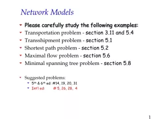
Learning Objectives After completing this chapter, students will be able to: • Connect all points of a network while minimizing total distance using the minimal-spanning tree technique • Determine the maximum flow through a network using the maximal-flow technique • Find the shortest path through a network using the shortest-route technique • Understand the important role of software in solving network problems
Chapter Outline 12.1 Introduction 12.2 Minimal-Spanning Tree Technique 12.3 Maximal-Flow Technique 12.4 Shortest-Route Technique
Introduction • This chapter covers three network models that can be used to solve a variety of problems • The minimal-spanning tree technique determines a path through a network that connects all the points while minimizing the total distance • The maximal-flow technique finds the maximum flow of any quantity or substance through a network • The shortest-route technique can find the shortest path through a network
Introduction • Large scale problems may require hundreds or thousands of iterations making efficient computer programs a necessity • All types of networks use a common terminology • The points on a network are called nodes and may be represented as circles of squares • The lines connecting the nodes are called arcs
Minimal-Spanning Tree Technique • The minimal-spanning tree technique involves connecting all the points of a network together while minimizing the distance between them • The Lauderdale Construction Company is developing a housing project • They want to determine the least expensive way to provide water and power to each house • There are eight houses in the project and the distance between them is shown in Figure 12.1
Minimal-Spanning Tree Technique • Steps for the minimal-spanning tree technique • Select any node in the network • Connect this node to the nearest node that minimizes the total distance • Considering all the nodes that are now connected, find and connect the nearest node that is not connected. If there is a tie, select one arbitrarily. A tie suggests there may be more than one optimal solution. • Repeat the third step until all nodes are connected
3 2 5 4 3 5 3 7 7 1 2 2 3 8 3 5 1 6 2 6 4 Gulf Minimal-Spanning Tree Technique • Network for Lauderdale Construction Figure 12.1
Minimal-Spanning Tree Technique • Start by arbitrarily selecting node 1 • The nearest node is node 3 at a distance of 2 (200 feet) and we connect those nodes • Considering nodes 1 and 3, we look for the next nearest node • This is node 4, the closest to node 3 • We connect those nodes • We now look for the nearest unconnected node to nodes 1, 3, and 4 • This is either node 2 or node 6 • We pick node 2 and connect it to node 3
Minimal-Spanning Tree Technique • Following this same process we connect from node 2 to node 5 • We then connect node 3 to node 6 • Node 6 will connect to node 8 • The last connection to be made is node 8 to node 7 • The total distance is found by adding up the distances in the arcs used in the spanning tree 2 + 2 + 3 + 3 + 3 + 1 + 2 = 16 (or 1,600 feet)
3 2 5 4 3 5 3 7 7 1 2 2 3 8 3 5 1 6 2 6 4 Gulf Minimal-Spanning Tree Technique • All iterations for Lauderdale Construction Figures 12.2 – 12.5
Maximal-Flow Technique • The maximal-flow technique allows us to determine the maximum amount of a material that can flow through a network • Waukesha Wisconsin is in the process of developing a road system for the downtown area • They want to determine the maximum number of cars that can flow through the town from west to east • The road network is shown in Figure 12.7 • The numbers by the nodes indicate the number of cars that can flow from the node
Maximal-Flow Technique • Four steps of the Maximal-Flow Technique • Pick any path from the start (source) to the finish (sink) with some flow. If no path with flow exists, then the optimal solution has been found. • Find the arc on this path with the smallest flow capacity available. Call this capacity C. This represents the maximum additional capacity that can be allocated to this route.
Maximal-Flow Technique • Four steps of the Maximal-Flow Technique • For each node on this path, decrease the flow capacity in the direction of flow by the amount C. For each node on the path, increase the flow capacity in the reverse direction by the amount C. • Repeat these steps until an increase in flow is no longer possible
2 2 1 2 East Point 6 1 1 3 0 West Point 1 2 1 0 1 10 4 1 6 1 5 3 2 0 3 Maximal-Flow Technique • Road network for Waukesha Capacity in Hundreds of Cars per Hour Figure 12.6
Maximal-Flow Technique • We start by arbitrarily picking the path 1–2–6 which is at the top of the network • The maximum flow is 2 units from node 2 to node 6 • The path capacity is adjusted by adding 2 to the westbound flows and subtracting 2 from the eastbound flows • The result is the new path in Figure 12.7 which shows the new relative capacity of the path at this stage
2 2 0 1 3 6 4 2 3 1 1 2 6 1 Maximal-Flow Technique • Capacity adjustment for path 1–2–6 iteration 1 Add 2 Subtract 2 Old Path New Path Figure 12.7
Maximal-Flow Technique • We repeat this process by picking the path 1–2–4–6 • The maximum capacity along this path is 1 • The path capacity is adjusted by adding 1 to the westbound flows and subtracting 1 from the eastbound flows • The result is the new path in Figure 12.8 • We repeat this process by picking the path 1–3–5–6 • The maximum capacity along this path is 2 • Figure 12.9 shows this adjusted path
2 6 0 1 2 3 4 4 6 0 1 2 1 1 0 4 0 1 2 1 2 0 0 1 10 4 1 6 1 5 3 2 0 3 Maximal-Flow Technique • Second iteration for Waukesha road system Add 1 Subtract 1 Old Path Figure 12.8 New Network
0 2 4 4 6 0 2 0 2 1 2 2 0 0 8 4 1 4 3 5 3 0 2 3 Maximal-Flow Technique • Third and final iteration for Waukesha road system Figure 12.9
Maximal-Flow Technique • There are no more paths from nodes 1 to 6 with unused capacity so this represents a final iteration • The maximum flow through this network is 500 cars
Shortest-Route Technique • The shortest-route technique finds how a person or item can travel from one location to another while minimizing the total distance traveled • It finds the shortest route to a series of destinations • Ray Design, Inc. transports beds, chairs, and other furniture from the factory to the warehouse • They would like to find the route with the shortest distance • The road network is shown in Figure 12.10
200 2 4 Plant 100 100 100 50 150 1 6 200 100 40 3 5 Warehouse Shortest-Route Technique • Roads from Ray’s plant to warehouse Figure 12.10
Shortest-Route Technique • Steps of the shortest-route technique • Find the nearest node to the origin (plant). Put the distance in a box by the node. • Find the next-nearest node to the origin and put the distance in a box by the node. Several paths may have to be checked to find the nearest node. • Repeat this process until you have gone through the entire network. The last distance at the ending node will be the distance of the shortest route.
Shortest-Route Technique • We can see that the nearest node to the plant is node 2 • We connect these two nodes • After investigation, we find node 3 is the next nearest node but there are two possible paths • The shortest path is 1–2–3 with a distance of 150 • We repeat the process and find the next node is node 5 by going through node 3 • The next nearest node is either 4 or 6 and 6 turns out to be closer • The shortest path is 1–2–3–5–6 with a distance of 290 miles
200 2 4 Plant 100 100 100 50 150 1 6 200 100 40 3 5 Warehouse Shortest-Route Technique • First iteration for Ray Design 100 Figure 12.11
100 200 2 4 Plant 100 100 100 50 150 1 6 200 100 40 3 5 Warehouse Shortest-Route Technique • Second iteration for Ray Design 150 Figure 12.12
100 200 2 4 Plant 100 100 100 50 150 1 6 200 100 40 3 5 Warehouse 150 Shortest-Route Technique • Third iteration for Ray Design 190 Figure 12.13
100 200 2 4 Plant 100 100 100 50 150 1 6 200 100 40 3 5 Warehouse 150 190 Shortest-Route Technique • Fourth and final iteration for Ray Design 290 Figure 12.14