Download
1 / 23
250 likes | 616 Views
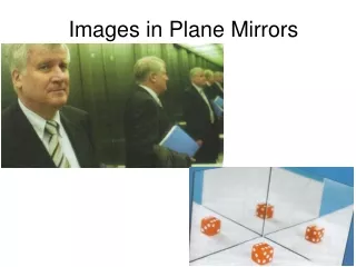
3.7. Magnification by plane mirrors. A plane mirror generates a virtual image that occurs as far into the mirror as the object is placed in front of the mirror and is the same size as the object . The magnification M of an optical system such as a mirror or lens is defined as.

E N D
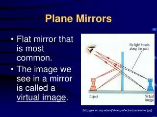
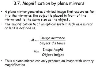
3.7. Magnification by plane mirrors • A plane mirror generates a virtual image that occurs as far into the mirror as the object is placed in front of the mirror and is the same size as the object . • The magnification M of an optical system such as a mirror or lens is defined as. • Thus a plane mirror can only produce an image with unitary magnification
P Q i H i i P Q 3.8. Sign Convention • The - sign in the expression for the magnification M is a consequence of the sign convention we will adopt. • We will use the real is positive sign convention. • If an object or image is real then it is a positive distance from the reflecting surface. This means that the image and object are formed on the same side of the mirror. • If an object or image is virtual then it is a negative distance from the mirror. • A real(virtua)l object and a virtual(rea)l image are always on opposite sides of the mirror.
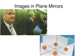
P Q i H i i P Q 3.8. Sign Convention • If we look at the image formed by a plane mirror it is evident that the image is erect i.e., pointing in the same vertical direction as the object. • The image is however virtual and so is given a negative distance. • Hence we would expect the magnification to be negative, but a negative magnification corresponds to an inversion of the image. • Thus we must include the - sign to ensure that the virtual image produced by a plane mirror is erect.
3.9. Reflections from Curved surfaces • The image size can be varied by use of a curved surface. There are several types of curved surface for example • Spherical • Parabolic • Elliptical • We will look at spherical surfaces. These come in two forms • Convex - like the back of a spoon • Concave - like the bowl of a spoon. • The curvature is set by the radius of curvature, R • A concave mirror has a positive radius of curvature • A convex mirror has a negative radius of curvature • Any line that is drawn to the mirror surface from the centre of curvature, a radius, strikes the surface at 90˚ and makes a normal to the surface.
3.10. Reflections at Curved Surfaces • To understand how a ray interacts with a curved surface we will make us of the paraxial approximation. This assumes that any ray propagating to a surface makes a small angle with the optic axis of the surface. • The optic axis is a line that pass through the centre of the surface at right angles to the surface.
3.11. Reflections at a Concave Surface • Any normal drawn at a concave surface is directed towards the optic axis. • Any ray that is incident on the mirror as shown below is reflected towards the optic axis.
3.11. Reflections at a Convex Surface • Any normal drawn at a convex surface is directed away from the optic axis. • Any ray that is incident on the mirror as shown below is reflected away from the optic axis.
3.12. The focal point of a curved surface • Consider a concave surface. A set of rays travel parallel to the optic axis as shown below. • The rays are all reflected such that they cross the optic axis at the same point. This point is known as the focal point and occurs a distance f, the focal length from the curved surface. • For a concave mirror the focal length is positive. • For a convex mirror the focal length is negative.
3.13. The relationship between the focal length and radius of curvature • A ray travels at a height h parallel to the optic axis. • The ray is incident on a concave mirror at angle i and is reflected to the focal point at an angle i. • From the figure it is evident that tani = h/R and tan2i = h/f. • By the paraxial approximation tani = i and so i = h/R and 2i = h/f. • Thus R = 2f.
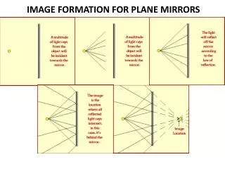
Consider a real object that is placed in front of a concave mirror. The image location can be found by considering the path of 4 rays drawn from the top of the object. The 4 rays follow the following paths: Ray 1: Parallel to the optic axis. This ray is reflected through the focal point of the mirror. Ray 2: Passes through the focal point of the mirror. This ray is reflected parallel to the optic axis. Ray 3: Passes through the centre of curvature of the mirror.This ray strikes the mirror at normal incidence and is reflected back on itself. Ray 4: Strikes the centre of the mirrorand is reflected symmetrically about the optic axis. The image is formed where the rays cross. 3.14. Image location by ray tracing
3.14 Ray Tracing O R F I Ray 1, Ray 2, Ray 3, Ray 4
3.15 Mathematical method for finding image location p O H1 H2 R F q I Let the object of height H1 be placed a distance p from the mirror of focal length f. The resulting image of height H2 is formed a distance q from the mirror.
3.15 Mathematical method for finding image location p a g i O H1 f s b e 2i F c R H2 q d I From triangle abc we get tans = H1/p From triangle deb we get tans = H2/q From triangle dfe we get tan2i = H2/(q-f) From triangle gfb we get tan2i = H1/f So H2/q = H1/p and H2/(q-f) = H1/f
3.15 Mathematical method for finding image location So H2/q = H1/p and H2/(q-f) = H1/f So H2/ H1 = q/p and H2/ H1 = (q-f) /f So q/p =(q-f) /f X both sides by fp qf = pq - pf / both sides by pfq 1/p = 1/f - 1/q Re-arrange to give This is the equation that links the focal length, object and image distances. NOTE
3.16 Examples of image location with a concave mirror We know that the focal length f, object distance p and image distance q are related by • Where is the image formed if: • A real object is located at infinity? • Here 1/p = 0. Thus q = f • The image is real and inverted • A real object is located at the radius of curvature, R. • Here p = R and R = 2f. • Thus p = 2f and so q = 2f. • Object and image located at the same plane. • The image is real and inverted.
A real object is located at f. • Here p = f and so 1/q = 0. • Image formed at infinity • The image is real and inverted • A real object is located at f/2 • Here 1/p = 2/f. Thus q = -f • So image formed is virtual. • The image is erect • When a real object is placed between the focal point and the concave mirror the image is virtual.
3.16 Why is an image real when p > f? O F R I When p > f the reflections from the concave mirror converge to a point on the same side of the mirror as the object. Hence the energy in the rays passes through the point where the image is formed.
3.16 Why is an image virtual when p < f? O I F When p < f the reflections from the concave mirror diverge. To find the point where the rays appear to cross they must be projected back into the mirror. Hence the image is virtual as the energy in the rays appears to come from the image.
3.17. Image formation by a convex mirror • For a convex mirror the focal length is negative. This means that the focal point of the mirror is located behind the curved surface. • As a result a real object placed anywhere in front of the mirror will produce a virtual image. • Why does this happen?
3.17. Image formation by a convex mirror • Here the rays always diverge and so image is found by tracing the rays back to the point where they appear to cross. O I F
3.18. Defects caused by reflections • We have assumed that the paraxial approximation applies in that all rays make small angles with respect to the optical axis. We also assume that the rays strike close to th e centre of the mirror. • In real systems the rays hit the whole mirror. We find that rays that hit near the outside of mirror are focused at a different point when compared with those that are close to the centre. • This causes a blurring of the image, and is known as spherical aberration. Note that to show the effect the reflection of the outer rays has been greatly exaggerated. The normals for the outer rays come from the same point as those for the inner rays. This problem is eliminated by use of a parabolic mirror.