Download
1 / 20
200 likes | 226 Views
This paper proposes a controlled open air test methodology for measuring and predicting the performance of 802.11 WLAN devices. The methodology involves utilizing a setup that reduces interference and multipath effects, taking channel measurements, and calibrating antennas for precise placement.

E N D
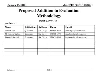
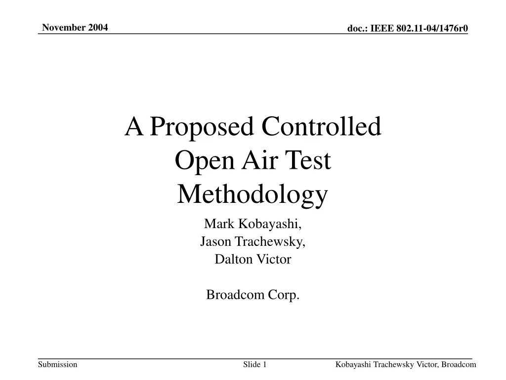
A Proposed ControlledOpen Air TestMethodology Mark Kobayashi, Jason Trachewsky, Dalton Victor Broadcom Corp. Kobayashi Trachewsky Victor, Broadcom
Agenda • Objective • Background • Goals • Theory of Ops • Block Diagram of setup • Picture of setup • Methodology • Test results • Recommendations Kobayashi Trachewsky Victor, Broadcom
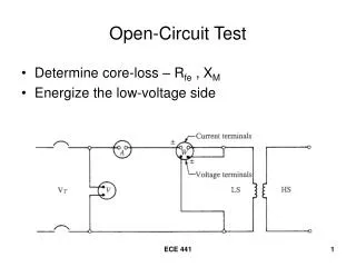
Objective • From PAR and 5 criteria: • Scope: The scope of 802.11T is to provide a set of performance metrics, measurement methodologies, and test conditions to enable measuring and predicting the performance of 802.11 WLAN devices and networks at the component and application level. (emphasis added) • Purpose: The purpose of 802.11T is to enable testing, comparison, and deployment planning of 802.11 WLAN devices based on a common and accepted set of performance metrics, measurement methodologies and test conditions. Kobayashi Trachewsky Victor, Broadcom
Background • The objective of TGT is to come up with a repeatable measurement methodology and to provide • set of metrics • measurement methodologies • test conditions Kobayashi Trachewsky Victor, Broadcom
Goals • Propose a controlled open air environment to help achieve the goals and objective of TGT • Allows for complete system evaluation including antenna and effects of other components of DUT Kobayashi Trachewsky Victor, Broadcom
REF DUT REF DUT REF DUT Cabled Channel Open Air Channel Theory of Operation • A purely conducted environment channel is essentially flat • An open air environment can have attenuation and several nulls created by multipath Purely Conducted Environment Channel representation of Purely Conducted Environment Open Air Environment Kobayashi Trachewsky Victor, Broadcom
REF DUT REF DUT DUT platform channel Open Air Channel Open Air Channel Theory of Ops Cont. • Open air channel can be broken into two components • The open air channel by itself • The DUT platform channel • DUT platform channel is a complex gain that varies with angle of arrival System Under Test (SUT) = * Kobayashi Trachewsky Victor, Broadcom
REF DUT DUT platform channel Open Air Channel Controlled Open Air Test • Create an environment where open air channel is virtually flat • reduce multipath channel response System Under Test (SUT) = * Kobayashi Trachewsky Victor, Broadcom
Overview Methodology • Utilize setup that severely reduces any interference from outside sources • Screen room • Use a directional antenna and RF absorbent material to reduce multipath effects • Take a channel measurement of the Open Air with no device present but place antenna in same position as where receive antenna would be in free space • Place DUT in place such that rx antenna is exactly in the place that was expected by step above • Utilize this measured free space channel loss to determine amount of received power as seen by the DUT • Measure transmitted power out to cabled portion add additional free space loss to determine rx channel power level Kobayashi Trachewsky Victor, Broadcom
AMP Network Analyzer Block DiagramOpen Air Calibration RF shielded screenroom • Main beam pattern of tx antenna pointed toward open end of RF enclosure to minimize multi-path channel effects • Keeps channel frequency response flat • Directional antenna focuses the majority of energy in a particular direction • Rx antenna is in the far field of the tx antenna • Amplifier puts received signal within rx sensitivity of network analyzer • Collect channel response to determine calibration Inner Walls lined with RF absorbent material calibrated antenna directional antenna Kobayashi Trachewsky Victor, Broadcom
REF DUT Variable Attenuator Block DiagramOpen Air Test RF shielded screenroom • Use power meter to measure tx power • Variable attenuator creates additional path loss for determining path loss sensitivity Inner Walls lined with RF absorbent material directional antenna Power meter directional coupler Kobayashi Trachewsky Victor, Broadcom
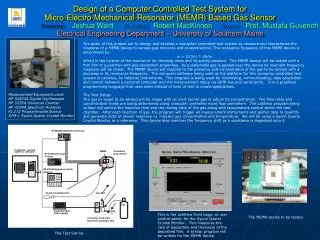
Picture of setup • Picture shows main components of items inside of the RF shielded enclosure • Items outside of enclosure are not shown RF shielded screenroom Inner Walls lined with RF absorbent material DUT directional antenna Kobayashi Trachewsky Victor, Broadcom
Plot from Network Analyzer • Channel 6 • Over the air measurement with DUT versus over the air measurement without the DUT over the air with DUT over the air without DUT Kobayashi Trachewsky Victor, Broadcom
Precision • Open air calibration measurements, requires precise placement (x,y,z) of the calibrated antenna and the actual DUT antenna. • Location of the RX calibrated antenna is key to a good measurement • Note the RX calibrated antenna can be a simple dipole. There is no need for a high-gain antenna like that used in the TX reference • Items utilized during all measurements need to be placed precisely in the same locations in all measurements • TX directional antenna needs to be in same location Kobayashi Trachewsky Victor, Broadcom
Product 1 PER Channel 1,6,13 conducted • Controlled experiment running conducted Kobayashi Trachewsky Victor, Broadcom
PER Channel 1,6,13 DUT channel with open air losses calibrated out • Note that after channel effects of air and DUT platform are calibrated out the curves line up similar to conducted results of previous slide Kobayashi Trachewsky Victor, Broadcom
Product 2 PER Channel 1-13 conducted • Controlled experiment running conducted Kobayashi Trachewsky Victor, Broadcom
PER Channel 13 DUT channel with open air losses calibrated out • Note that after channel effects of air and DUT platform are calibrated out the curves line up similar to conducted results of previous slide Kobayashi Trachewsky Victor, Broadcom
Issues • Requires a very accurate positioner • Requires knowledge of the exact location of the antenna(s) in the DUT (sometimes enclosed in the chassis) • Do not currently have a good proposed technique for testing diversity systems (TBD) • Have not yet checked that the procedure works at all incident azimuth angles • Do not have solution to run the test easily over a variety of elevation angles • The resulting RF channel isn’t completely flat; so, while we are calibrating the rx power at a point in space, we really want to calibrate capacity (integral of the logarithm of SNR at high SNR) Kobayashi Trachewsky Victor, Broadcom
Recommendation • TGT should continue to explore this methodology (as alluded to in slide 6) for doing full system characterization via Open Air Testing Kobayashi Trachewsky Victor, Broadcom