Download
1 / 12
120 likes | 288 Views
Proposed Addition to Evaluation Methodology. Authors:. Date: 2010-01-18. Background. Evaluation Methodology 09/0296 [1] in its current form Specifies the following three simulation scenarios Home living room; Office conference room; and Enterprise cubicle

E N D
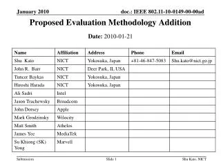
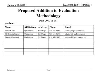
Proposed Addition to Evaluation Methodology Authors: Date:2010-01-18
Background • Evaluation Methodology 09/0296 [1] in its current form • Specifies the following three simulation scenarios • Home living room; Office conference room; and Enterprise cubicle • Does not consider limitation on beam steering capability of devices in any of the three scenarios • Some constraint on antenna capabilities of handheld devices is needed to get a realistic performance evaluation • The scenarios with multiple devices assume an infrastructure network with an Access Point (AP) that has good link quality to all other devices • 11ad technology should enable the proliferation of 60GHz in devices without being dependent on the market for 60GHz APs
An Important Use Case • 60GHz devices should be able to form a peer-to-peer network with limited-capability devices • Consisting of battery-operated low complexity devices such as smart phones • Such devices have limited form factor, power, and beamforming capabilities • Large phased arrays or several beam-switched antennas puts a high power requirement on many handheld devices • Constraints on where the antennas and antenna assemblies can be placed were also mentioned in 09/1153 [2] • A ceiling-mounted device (AP) that is connected to a power source may not be present • Example settings: cafés, lounges, and some conference rooms • In line with some usage scenarios specified in 07/2988 [3]
Proposed Modifications to the Conference Room Scenario • We propose the following modifications to the existing Conference Room setting to enable a scenario with limited-capability devices • The AP may or may not have a 60 GHz radio. • Add an additional handheld device, replacing one of the laptop devices • Handheld devices will be limited to have beamwidth (HPBW) >= 60o • If the AP does not have a 60 GHz radio, communication with AP for 2 devices is optionally replaced by a peer-to-peer communication between the 2 devices. • Does not require new channel models • Current measurements and models on the conference room setting [4] remain applicable
Specific Changes to 09/0296r144.3.2 (1/6) In Section 4.3.2, make the following changes: Mix of uses: Laptop transmitting lightly compressed video to projector. Multiple laptops connected to an AP thatin the default scenario has a 60 GHz radio; and in the optional scenario does may or may not have a 60 GHz radio. Laptop connected to device performing sync-and-go file transfer. Laptops connected to other laptops performing local file transfer. Links between devices are logical, e.g. STA 3 and STA 5 are performing local file transfer between each other but the physical link could be direct or through the AP. Note: In the optional scenario where Ifthe AP does not have a 60 GHz radio, then all client-to-AP communication is assumed to occur using other bands such as the 2.4 or 5 GHz band.
Specific Changes to 09/0296 4.3.2 (2/6) Replace Fig. 1 with the following:
Specific Changes to 09/0296 4.3.2 (3/6) • Configuration • Room dimensions (length, width, height) in meters is 3.0 x 4.5 x 3 • Devices (coordinates of devices are calculated using coordinate axes shown in Figure 1 • AP (may or may not have a 60 GHz radio): location (x = 1.50 m, y = 0.50 m, z = 2.90 m – in ceiling) • STA 1: • Projector • Location: ( x = 1.75 m, y =2.30 m, z fixed at 1 m) • Traffic type: receiving lightly compressed video from STA 2 (LOS link) • STA 2: • Mobile Device Laptop • Location: (x = 1.90 m, y = 1.50 m, z fixed at 1m) • Traffic type: • Transmitting lightly compressed video to STA 1 (LOS link) with target bit rate (p) equal to TBD Mbps • Local file transfer from AP. • Antenna capability: >=60 degree HPBW pointed towards STA 1.
Specific Changes to 09/0296 4.3.2 (4/6) • STA 3: • Laptop • Location: (x = 1.35 m, y = 3.00 m, z fixed at 1m) • Traffic type: • Local file transfer to/from STA 5 (NLOS link) • Web browsing • STA 4: • Laptop • Location: (x = 1.30 m, y = 2.40 m, z fixed at 1m) • Traffic type: • Local file transfer to AP • Web browsing • STA 5: • Laptop • Location: (x = 1.25 m,y = 1.40 m, z fixed at 1m) • Traffic type: • Local file transfer to/from STA 3 (NLOS link) • Web browsing (if AP has a 60 GHz radio) or file transfer to STA 7 (if the AP does not have a 60 GHz radio).
Specific Changes to 09/0296 4.3.2 (5/6) • STA 6: • Laptop • Location: (x = 1.55 m, y = 1.20 m, z fixed at 1m) • Traffic type: web browsing • STA 7: • Laptop • Location: (x = 1.85 ,y = 3.10, z fixed at 1m) • Traffic type: • Local file transfer to STA 8 (LOS link) • Local file transfer from AP (if the AP has 60 GHz radio) or file transfer from STA 5 (if AP does not have a 60 GHz radio). • STA 8: • Mobile device • Location: (x = 1.60, y = 3.25, , z fixed at 1m) • Traffic type: Local file transfer from STA 7 (LOS link) • Antenna capability: >= 60 degree HPBW pointed towards STA 7
Specific Changes to 09/0296 4.3.2 (6/6) • PHY channel impulse and pathloss model • Office conferenceroom • All links to the AP are LOS links that may be blocked by people. Model of the human blockage is TBD. Type of links (LOS or NLOS) between two STAs is specified above. • The following non-communicating pairs have NLOS channels: STA2 STA7, STA2 STA8, STA6 STA7, STA1STA8. All other pairs have LOS channels, except due to human blockage. • TBD definition of interference depending on topology
Summary • Some modifications to the Conference Room setting are proposed to enable modeling of an ad-hoc network with limited-capability devices • Limited beamforming capabilities in handheld devices • Absence of ceiling-mounted Access Point with large steering capability (for anytime anywhere conferencing) • All existing scenarios in the evaluation methodology, channel models, and measurements remain valid • Suggestions for improving the scenario are welcome
References [1] E. Perahia, “TGad Evaluation Methodology,” 802.11-09/0296, 11-19-2009. [2] C. Cordeiro et al., “Motivation and Requirements on 60 GHz Beamforming,” 802.11-09/1153r2. [3] A. Myles et al., “Wi-Fi Alliance (WFA) VHT Study Group Usage Models,” 802.11-07/2988r4. [4] A. Maltsev et al., “Channel Models for 60 GHz WLAN Systems,” 802.11-09/0334r4.