Download
1 / 18
180 likes | 202 Views
CREZ - Voltage Profiles on Series Compensated Lines. Prepared by Paul Hassink with AEPSC ERCOT RPG, 11/11/11. Series Capacitor (SC). Voltage Profile Characteristics ERCOT SC installations CREZ Reactive Study Techniques for Reducing Voltages Location Segmentation Switched Shunts.

E N D
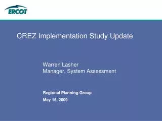
CREZ - Voltage Profiles on Series Compensated Lines Prepared by Paul Hassink with AEPSC ERCOT RPG, 11/11/11
Series Capacitor (SC) • Voltage Profile Characteristics • ERCOT SC installations • CREZ Reactive Study • Techniques for Reducing Voltages • Location • Segmentation • Switched Shunts Prepared by AEPSC WTP
Upgrading Existing 345 kV South Texas system Receiving-end Series Capacitors (12/25 ohm segments) Segmented Series Capacitors (24 ohm) Prepared by AEPSC WTP
CREZ Series Capacitors Series Capacitor Prepared by AEPSC WTP
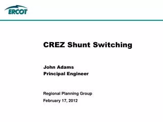
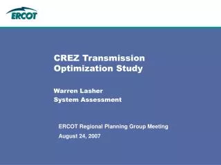
ERCOT CREZ Reactive Power Compensation Study Prepared by AEPSC WTP
Source End SC Voltages Relative to Impedance MW flow line SC Voltage 10% |Impedance| 0% 150% Prepared by AEPSC WTP
Mid-Line SC Voltages Relative to Impedance MW flow SC ½ of line ½ of line Voltage 10% |Impedance| 0% 150% Prepared by AEPSC WTP
Mid-Line SC Voltages Relative to Impedance High MW flow ½ of line ½ of line SC Voltage 10% |Impedance| 0% 150% Prepared by AEPSC WTP
Voltage Constraints • Source and Sink end voltages should be operable across system voltages of 98% to 104% under normal conditions • Post contingency, voltages must remain within a 90% to 110% window • When voltages fall below 95% or exceed 105%, automatic action must regulate voltages back into voltage window within seconds • Voltages within line segments or the series capacitor must be greater than 80% to avoid voltage instability (high reactive losses) Prepared by AEPSC WTP
Case Study – Big Hill to Kendal Series Capacitors • Two Segments at 24 ohms each • 3600a continuous and 4000a emergency rating • Located within TNC footprint for maintenance and operations • Roughly 25% and 50% from sending end (Big Hill) Prepared by AEPSC WTP
SC Scenarios @ 50% compensation • No Series Compensation • Sending-end installation in one bank • Mid-line installation in one bank • Segmented Mid-line installation @ 3600a • Segmented Mid-line installation @ 4300a Prepared by AEPSC WTP
SC Bypassed @ Rated Current ~ continuous rating of SC 3200 Mvar reactive line losses 80% voltage mid-line ~ 150 MW losses 80o phase shift Prepared by AEPSC WTP
SC Inserted on Sending-end near Rated Current Reactive power enters SC 2100 Mvar reactive line losses 125% voltage ~ 120 MW losses 30o phase shift Prepared by AEPSC WTP
SC Inserted on Sending-end with Capacitor near Rated Current Reactive power exits SC 116% voltage ~ 150 MW losses 37o phase shift Prepared by AEPSC WTP
SC Inserted Mid-line Single Segment @ Rated Current ~ continuous rating of SC 110% voltage 30o phase shift ~ 144 MW losses Prepared by AEPSC WTP
SC Inserted Mid-line Two Segments @ Rated Current Incremental 400MW ~ continuous rating of SC 3.5% voltage bandwidth ~ 150 MW losses 30o phase shift Prepared by AEPSC WTP
SC Inserted Mid-line Two Segments @ Emergency Current Short time emergency rating of SC 105% voltage ~ 220 MW losses 38o phase shift Prepared by AEPSC WTP
SC Inserted Mid-line with Capacitor@ Emergency Current Short time emergency rating of SC 104% voltage ~ 220 MW losses 39o phase shift Prepared by AEPSC WTP