Download
1 / 14
140 likes | 159 Views
UC CubeCats' project focuses on building an omnidirectional double cross antenna to pull weather satellite images. Using inexpensive hardware, the team aims to understand antenna design, satellite communication protocol, and decode NOAA images. Through hardware and software configurations, the team tests, improves, and processes image data for valuable insights. Lessons learned include antenna design, code trans-coding, and WAV audio signal decoding for static images. Future plans involve automatic satellite detection, rotor control, and communication with LEO satellites.

E N D
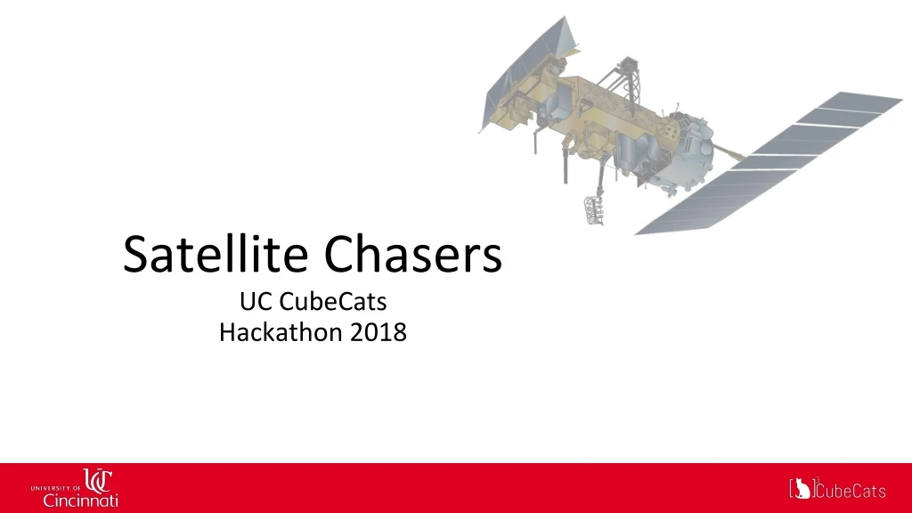
Satellite Chasers UC CubeCats Hackathon 2018
Who are we UC CubeCats is a student organization that is dedicated to educating students through the construction and launch of Cube Satellites (CubeSats) and High Altitude Balloons. Hackathon Team: Jessica Kropveld Reeve Lambert Aaron Boyd Daniel Taylor
Mission • Use an omnidirectional double cross antenna to pull images from National Oceanic and Atmospheric Administration weather satellites • Gain an understanding of Antenna design and satellite communication protocol • Use inexpensive hardware (< $50) NOAA Polar Orbit Weather Satellite
Research Image decoding software Antenna configuration Scheduling satellite passes
Design Hardware used: 14ft of 50Ω coaxial cable, 4 L-brackets, 8 copper brackets, 8 steel dipoles, 12 ft of wood. Software used: SDR#, WXtoIMG, NOAA online tracker.
Build Soldering the coaxial cable to the dipoles Bracing the dipole supports Separating the coaxial cables and grounding the antenna
Testing SDR# interface focusing in on satellite transmission Team testing antenna Team posing with antenna after a successful test
Improvement Process • APRS packets - 1:30 am • Preliminary testing with local HAM radio • NOAA 19- 4:09 am (56°) • Inconclusive, needed to configure settings • NOAA 15 - 7:23 am (76°) • Compensated for doppler shift • NOAA 18 - 8:37 am (84°) • Adjusted sampling rate to match satellite specs • NOAA 15 - 9:05 am (14°) • Final test, good images
Raw Results First conclusive test image, note high distortion and weak signal Raw image of cloud cover collected in final test. Yellow plus sign indicates our location.
Processed Results False color cloud cover NOAA 15 Thermal overlay filter NOAA 18
Processed Results Sea Surface Temperature NOAA 18 Cloud Cover over US NOAA 18
Lessons Learned Next Steps • How to calculate and design an antenna for proper gain of a desired frequency • How to use SDR# to trans-code images from an analog signal • How to decode a wav audio signal from a satellite into a static image • Automate antenna • automatic satellite detection and alert system • rotor control • Try for higher frequency and geostationary satellites • Apply lessons learned to the UC CubeCats Ground Station for communicating with Low Earth Orbit (LEO) Satellites
Collecting Data Explanation: This is the SDR# interface collecting data as the satellite passes over Cincinnati. The inclination and distance of the satellite can affect noise and image quality. Our team has focused in on a specific frequency to listen in on the satellite. The high pitched noise is the regular satellite transmission. The softer ticking in the background is the metronome timer attached to the transmissions. After collecting suitible data, it is decoded with WXtoIMG into an image for post-processing.