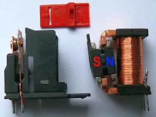
A relay
A relay. V acuum tubes. ENIAC: 17, 468 vacuum tubes, 70,000 resistors, 10,000 capacitors, 1,500 relays, 6,000 manual switches, 5 million hand-soldered joints … Not a stored program computer. 1946. EDSAC (Electronic Delay Storage Automatic Calculator):

A relay
E N D
Presentation Transcript
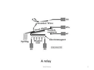
A relay Early history
Vacuum tubes Early history
ENIAC: 17, 468 vacuum tubes, 70,000 resistors, 10,000 capacitors, 1,500 relays, 6,000 manual switches, 5 million hand-soldered joints … Not a stored program computer. 1946.
EDSAC (Electronic Delay Storage Automatic Calculator): University of Cambridge Mathematical Laboratory, England, 1949. 1 K 18-bit words of memory, in mercury delay tubes. First practical stored-program computer. Subroutines were used! (The word “compiler” originated here.)
A magnetic drum at work Early history
Core memory: 1 ferrite core = 1 bit Early history
An IBM 7090 computer Early history
The control panel of an IBM 360 computer Early history
Inside the CPU there are three registers: • The instruction register: IR (20 bits, i.e., one word) • The instruction counter: IC (16 bits, i.e., an address) • The accumulator: A (20 bits, i.e., one word) • A program is composed of one-word instructions. • The instruction counter (IC) holds the address of the next instruction to be executed. • The instruction register (IR) holds the instruction that is being executed. Here is the format of an instruction: • opcode operand • 4 bits 16 bits Early history
The CPU cycle: The processor performs a very simple sequence of actions, over and over again: Load the word at address IC into IR: IR := m[ IC ]. Increment IC: IC := IC + 1. Perform the action prescribed by the instruction in IR. Repeat from step 1 (unless it was a halt instruction) Early history
0 HLT a HALT the machine, after loading MA with a. 1 STO a STORE the accumulator: m[ a ] := A . 2 LOA a LOAD into the accumulator: A := m[ a ] . 3 AND a Bitwise AND: A := A bit_and m[ a ] . 4 OR a Bitwise OR: A := A bit_or m[ a ] . 5 XOR a Bitwise exclusive OR: A := A bit_xor m[ a ] . 6 LSH a Logical SHift(right if a positive, left otherwise) 7 ASH a Arithmetic Shift (with sign-extension) 8 ADD a ADD: A := A + m[ A ] 9 SUB a SUBTRACT: A := A – m[ A ] A JMP a JUMP: IC := a B JMZ a JUMP on Zero: if A = 0 then IC := a fi C JMN a JUMP on Negative: if A < 0 then IC := a fi D CAL a subroutine CALL: m[ a ] := IC; IC := a + 1 E RET a subroutine RETURN: IC := m[ a ] F DEV i DEVICE operation Early history
0 HLT a 1 STO a 2 LOA a 3 AND a 4 OR a 5 XOR a 6 LSH i 7 ASH i 8 ADD a 9 SUB a A JMP a B JMZ a C JMN a D E F ;; Add a sequence of integers that ends with zero. ;; Leave the result in the accumulator. LOA DATA ; the next integer JMZ DONE ; if zero then end of data ADD SUM ; add to the running sum … STO SUM ; and save it … DONE LOA SUM ; result to accumulator HLT 0 ; SUM LIT 0 ; the sum so far ; DATA … LIT 0 ; end of data END Early history
0 HLT a 1 STO a 2 LOA a 3 AND a 4 OR a 5 XOR a 6 LSH i 7 ASH i 8 ADD a 9 SUB a A JMP a B JMZ a C JMN a D E F ;; Add a sequence of integers that ends with zero. ;; Leave the result in the accumulator. LOOP LOA DATA ; the next integer JMZ DONE ; if zero then end of data ADD SUM ; add to the running sum … STO SUM ; and save it JMP LOOP ; DONE LOA SUM ; result to accumulator HLT 0 ; SUM LIT 0 ; the sum so far ; DATA … LIT 0 ; end of data END It is now time to add the next integer. But just adding the green instruction will not do the trick. Why? Early history
0 HLT a 1 STO a 2 LOA a 3 AND a 4 OR a 5 XOR a 6 LSH i 7 ASH i 8 ADD a 9 SUB a A JMP a B JMZ a C JMN a D E F ;; Add a sequence of integers that ends with zero. ;; Leave the result in the accumulator. LOOP LOA DATA ; the next integer JMZ DONE ; if zero then end of data ADD SUM ; add to the running sum … STO SUM ; and save it LOA LOOP ; prepare for the next integer: ADD ONE ; increment the operand STO LOOP ; of the first LOA instruction JMP LOOP ; iterate ; DONE LOA SUM ; result to accumulator HLT 0 ; SUM LIT 0 ; the sum so far ONE LIT 1 ; the constant 1 ; DATA … LIT 0 ; end of data END Early history
The ability to perform automodification was considered a great advantage of the “von Neuman” machine. That is, the “stored program” computer. Arthur W. (Arthur Walter) Burks, Herman Heine Goldstine, John Von Neumann; Preliminary Discussion of the Logical Design of an Electronic Computer Instrument; (Institute for Advanced Study, January 1, 1946) ASIN B0007HW8WE + earlier ideas of Alan Turing, Prosper Eckert, John Mauchly … Early history
The ability to perform automodification was considered a great advantage of the “von Neuman” machine. With experience, and as progress made more registers affordable, we came to a very different conclusion. There were even some machines that made it almost impossible to modify the code memory (e.g., PDP 11/70). What are the advantages of that? Early history
The ability to perform automodification was considered a great advantage of the “von Neuman” machine. With experience, and as progress made more registers affordable, we came to a very different conclusion. There were even some machines that made it almost impossible to modify the code memory (e.g., PDP 11/70). What are the advantages of that? Why “almost” ? Early history
While the idea of automodification of programs fell into disfavour relatively quickly, it took some time before there was any hardware support for a stack. The subroutine calling sequence of the A1 was typical. So recursion was quite expensive, and considered an exotic luxury. Early history
While the idea of automodification of programs fell into disfavour relatively quickly, it took some time before there was any hardware support for a stack. The subroutine calling sequence of the A1 was typical. So recursion was quite expensive, and considered an exotic luxury. This might seem strange to us now, but in those days machines were so incredibly expensive (and slow) that making efficient use of the computer was the highest priority. Early history
;; GCD in A1: BSS 2 ; arguments GCD BSS 1 ; the entry point STO GCD – 1 ; store the first argument GCD_LOOP LOA GCD – 1 ; A SUB GCD – 2 ; B JMZ GCD_EXIT ; A = B ? JMN GCD_LT ; A < B STO GCD – 1 ; A <- A – B JMP GCD_LOOP ; iterate ; GCD_LT LOA GCD – 2 ; B SUB GCD – 1 ; B – A STO GCD – 2 ; B <- B – A JMP GCD_LOOP ; iterate ; GCD_EXIT LOA GCD – 1 ; result RET GCD ; return Early history
C GCD IN FORTRAN II: 1 IF ( A – B ) 5, 9, 2 2A = A – B GOTO 1 5 B = B – A GOTO 1 9 GCD = A RETURN END A Hollerith card IBM 029 card punch Early history 19th century punch
C GCD IN FORTRAN IV 1 IF ( A .EQ. B ) GOTO 9 IF ( A .LT. B ) GOTO 2 A = A – B GO TO 1 2 B = B – A GOTO 1 9 GCD = A RETURN END C GCD IN FORTRAN II 1 IF ( A – B ) 5, 9, 2 2A = A – B GOTO 1 5 B = B – A GOTO 1 9 GCD = A RETURN END Early history