Simulation of Interdigitated Electrodes for Dielectrophoretic Cell Sorting
40 likes | 217 Views
Simulation of Interdigitated Electrodes for Dielectrophoretic Cell Sorting. Dielectrophoresis (DEP). Methods (cont.). Analysis. DEP is a phenomenon wherein a nonuniform AC electric field polarizes a particle, exerting a force on it. This force is approximated by the equation

Simulation of Interdigitated Electrodes for Dielectrophoretic Cell Sorting
E N D
Presentation Transcript
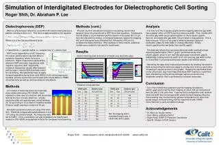
Simulation of Interdigitated Electrodes for Dielectrophoretic Cell Sorting Dielectrophoresis (DEP) Methods (cont.) Analysis DEP is a phenomenon wherein a nonuniform AC electric field polarizes a particle, exerting a force on it. This force is approximated by the equation Where fCM is the Clausius-Mossotti factor: ε = permittivity, r = particle radius, ω = angular freq, E = electric field The first round of simulations focused on visualizing electric field squared, since it is proportional to DEP force (see equation). Subsequent rounds added a 10 µm diameter particle injector in the upper left (10 µm from the inlet and the ceiling), to compare distances required for trapping. 400 µm/s flow speed was simulated first, followed by 500 µm/s to compare the best performers. After analysis of those results, additional models were created to test specific hypotheses. It is clear from the E-square graphs and the trapping data that gap width has a greater effect on DEP force than electrode width. First, models with the same gap width are grouped together on the E-square graphs. Second, all models with gap width 100 µm failed to trap particles. This is likely because 100 µm is too great a distance between adjacent electrodes’ edges for their fields to overlap effectively. Finally, elec50_gap25 performed better than elec25_gap50. The data also shows that narrowing electrode width eventually stops improving performance; Elec17_gap17 performed worse than elec25_gap25, which in turn had little advantage over elec50_gap25. Additionally, holding electrode width at 50 and reducing gap width further to 10 and then 5 µm produced the best results of all models tested. Narrowing the gaps likely improved performance by enabling the electric fields surrounding the electrode edges to overlap and reinforce each other, increasing E-square as seen in the graphs. Keeping the electrodes wider, on the other hand, may have helped because DEP requires a nonuniform field, and spacing out the strong-field gap regions produces more lengthwise variation than is generated by narrower electrodes. Results DEP force's dependence on AC frequency for a given particle type is sigmoid about a crossover frequency, where no force is produced. Higher frequencies yield positive, attractive DEP, and lower frequencies yield negative, repulsive DEP. Importantly, crossover frequencies usually differ between particle types, making DEP potentially useful for cell sorting. We specifically hope to apply it toward separating neural stem cells (NSCs) from nonhomogeneous samples, and are performing real-life tests with mouse NSCs in PDMS microchannels, as well as running computer simulations. Electric field squared as function of height over electrode edge: Distance to trap particles: Roger Shih, Dr. Abraham P. Lee Conclusion Methods Out of the models that underwent particle trapping simulations, elec50_gap5 performed the best, trapping at about 105 µm downstream from the inlet in 500 µm/s flow. It seems that a configuration with medium electrode width and narrow gap width yields the best trapping efficiency. Future testing may involve finding optimal configurations for other flow speed ranges, and performing real-life experiments with PDMS microchannels to verify simulation findings. 2-D models of electrode-lined microchannels were constructed using CFD-GEOM. Each represent a side-view of a channel, with electrodes forming the floor of every other box. Initially, electrode width and spacing were varied between 25, 50, and 100 µm, for a total of 9 starting models. Channel height was kept constant at 50 µm. Acknowledgements Simulation parameters were set using CFD-ACE- GUI. Electrode voltages alternated between 0 and 10 V along the channel length. AC frequency was set to 5 MHz. Once a simulation run was completed, the results were viewed in CFD-VIEW, and graphed in Excel for comparison and planning. • Dr. Abe Lee, faculty mentor • Lisen Wang, graduate mentor • Stuart Ross, SURF-IT Research Coordinator • Said M. Shokair, UROP Director NA: No trapping within simulated length (usu. 3 electrodes and 2 gaps). S ummer U ndergraduate 2R esearch 0F ellowship in 0I nformation6T echnology Roger Shih · www.research.calit2.net/students/surf-it2006 · www.calit2.net