Download
1 / 28
330 likes | 705 Views
“ Plasmatron” Plasma Exciter. Developed in Conjunction with Advanced Energy Industries, Inc. Voorhees, NJ. Joseph E. Palaia, IV. EE415 Electrical Engineering Senior Project New Jersey Institute of Technology - Mt. Laurel, NJ.

E N D
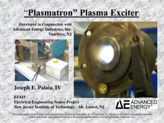
“Plasmatron” Plasma Exciter Developed in Conjunction with Advanced Energy Industries, Inc. Voorhees, NJ Joseph E. Palaia, IV EE415 Electrical Engineering Senior Project New Jersey Institute of Technology - Mt. Laurel, NJ This presentation contains data proprietary to Advanced Energy Industries, Inc. of Voorhees, NJ. It's use is restricted to academic evaluation unless specifically approved in writing by a designated representative of Advanced Energy Industries, Inc.
Project Definition : • 131,838,538 passenger cars were registered in 1998 in the US, this number increases each year. • More cars = more pollution. • How can we preserve our natural environment and yet maintain our way of life? This slide contains data proprietary to Advanced Energy Industries, Inc. of Voorhees, NJ. It's use is restricted to academic evaluation unless specifically approved in writing by a designated representative of Advanced Energy Industries, Inc.
The Proposed Solution : • Plasma reforming of fossil fuels. • A plasma provides energy to increase reaction rates and break down complex hydrocarbon molecules in fossil fuels, causing the releasing of hydrogen. • We add this hydrogen to the internal combustion engine along with roughly ¾ of the usual fuel flow. • The hydrogen acts as a “super-oxygenator”, allowing for more complete combustion. • The result is a drastic reduction of polluting chemical such as NOx and CO as well as more complex species. • Experimentation has shown as much as a 100X reduction. This slide contains data proprietary to Advanced Energy Industries, Inc. of Voorhees, NJ. It's use is restricted to academic evaluation unless specifically approved in writing by a designated representative of Advanced Energy Industries, Inc.
How does this project fit in? • Massachusetts Institute of Technology, Plasma Science Fusion Center proposed this solution and has been experimenting for the past several years. • Two year ago, Advanced Energy was approached to conduct preliminary research on how to generate the plasma. • They were asked to provide prototype generators to support the research going on at MIT. • As an intern at Advanced Energy, I have been responsible for performing that research and for supplying those generators. This slide contains data proprietary to Advanced Energy Industries, Inc. of Voorhees, NJ. It's use is restricted to academic evaluation unless specifically approved in writing by a designated representative of Advanced Energy Industries, Inc.
Plasma? • The plasma is basically just a spark with material flowing through it (fuel in the case of a car, air for demonstration purposes). • In order to generate this plasma, we have to use the power available, ie the 12V or 24V system present in cars and trucks. • To create a spark across a gap requires a voltage sufficient to break down the dielectric in the gap (fuel or air). A typical rule of thumb is 1kV / mm of gap. This slide contains data proprietary to Advanced Energy Industries, Inc. of Voorhees, NJ. It's use is restricted to academic evaluation unless specifically approved in writing by a designated representative of Advanced Energy Industries, Inc.
Generator Specifications : 1. Input DC Voltage: 12V, 24V, or 42V 2. Frequency: 200kHz 3. Power Level : as much as 1kW at 200kHz 4. DC/AC Conversion Efficiency: >60%, for car >80% 5. Output Voltage 10kV to 20kV at specified frequency, depending upon gap distance 6. Size: Generator Box (5” by 6” by 9”) Transformer Box (5” by 6” by 4” deep) 7. Operating Temperature: Room temperature (for car 0 to 175 degrees F) 8. DC Power Input Connections: Two wire connections (for car, one wire + chassis ground). 9. Output HV Connections: HV wire connection with ground return terminal. (for car, HV wire connection) 10. Cooling Conditions: Utilization of DC Fan(s) to cool generator. 11. Logic Supply Connections: Separate, external terminals (for car, logic driven off same supply as power) 12. Finished Cost of Prototype: <$300 This slide contains data proprietary to Advanced Energy Industries, Inc. of Voorhees, NJ. It's use is restricted to academic evaluation unless specifically approved in writing by a designated representative of Advanced Energy Industries, Inc.
So what’s the project? • Generating the necessary voltage to break down the spark gap, and matching the generator to the load is the project at hand. • It has involved : • The creation of the necessary circuitry. • Rough bread-boarding of the circuit and initial testing. • PC Board design for integration into an early package. • Production of a fully operational prototype. • Testing and improving that prototype. This slide contains data proprietary to Advanced Energy Industries, Inc. of Voorhees, NJ. It's use is restricted to academic evaluation unless specifically approved in writing by a designated representative of Advanced Energy Industries, Inc.
How does it work? • We want to generate 20,000V in order to break down the required spark gap. We are supplied 12 or 24Vdc. • A good way to get this voltage step-up is through transformer action, which however, requires an AC input. • Now the task is simply DC to AC conversion, realizable through a variety of possible switching scenarios. • It was decided to implement a push-pull scheme to achieve this conversion. • In a push-pull amplifier, the DC voltage is alternately switched through the primaries of two transformers. The secondaries of these transformers are connected out of phase, which results in the creation of a sinusoidal signal. In effect, one side of the amplifier swings the output above the reference, the other swings it below. This slide contains data proprietary to Advanced Energy Industries, Inc. of Voorhees, NJ. It's use is restricted to academic evaluation unless specifically approved in writing by a designated representative of Advanced Energy Industries, Inc.
How does it work? • To realize a push-pull amplifier, it is necessary to provide two logic signals to the gates of power mosfets. For proper switching, it is necessary that these signals remain 180% out of phase. This is achieved through utilization of the circuitry below. This slide contains data proprietary to Advanced Energy Industries, Inc. of Voorhees, NJ. It's use is restricted to academic evaluation unless specifically approved in writing by a designated representative of Advanced Energy Industries, Inc.
Schematic Diagrams: This slide contains data proprietary to Advanced Energy Industries, Inc. of Voorhees, NJ. It's use is restricted to academic evaluation unless specifically approved in writing by a designated representative of Advanced Energy Industries, Inc.
Circuit Development: • Throughout the course of design and initial circuit prototyping, a number of individuals at Advanced Energy have lent assistance and their expertise. • Early in the development I went through a design review with the engineers of that facility.Their recommendations have influenced the path the design has followed since that time. • Also, my mentor, Dr. Anton Mavretic, has provided a great deal of insight. He provided the initial circuit concept. • Since that time; through experimentation, prototyping, testing, and analysis; I have changed the circuit and directed the course of development. I have added components and changed the circuit layout based upon the performance of the built prototypes. • Sometimes I try things on my own and sometimes I refer to the other engineers at AE. This slide contains data proprietary to Advanced Energy Industries, Inc. of Voorhees, NJ. It's use is restricted to academic evaluation unless specifically approved in writing by a designated representative of Advanced Energy Industries, Inc.
What was done recently? • Some work had been completed prior to EE413/ EE415, and several prototype units with hand soldered circuitry had been sent to MIT for testing. • What remained to be done at the beginning of EE415 : • Design of printed circuit boards. • Cutting and population of these boards. • Refined prototype package buildup. This slide contains data proprietary to Advanced Energy Industries, Inc. of Voorhees, NJ. It's use is restricted to academic evaluation unless specifically approved in writing by a designated representative of Advanced Energy Industries, Inc.
Project Schedule : 1/1/02 – 1/22/02 TaskEstimated TimeDeadline Power Section PC Board Design 12 Hours 1/10/02 Logic Section PC Board Design 12 Hours 1/22/02 1/23/02 – 2/13/02 TaskEstimated TimeDeadline Cut Logic & Power Boards 24 Hours 1/30/02 Populate Boards 24 Hours 2/6/02 Initial Board Testing 4 Hours 2/13/02 2/14/02 – 3/7/02 TaskEstimated TimeDeadline Cut BUD box 4 Hours 2/18/02 Mount fan, switch, etc. 6 Hours 2/24/02 Mount heat sink & PC Boards 4 Hours 3/7/02 3/8/02 – 3/29/02 TaskEstimated TimeDeadline Complete assembly and packaging 10 Hours 3/21/02 Begin testing and minor modifications 15 Hours 3/29/02 3/30/02 – 4/20/02 TaskEstimated TimeDeadline Final testing 5 Hours 4/8/02 This slide contains data proprietary to Advanced Energy Industries, Inc. of Voorhees, NJ. It's use is restricted to academic evaluation unless specifically approved in writing by a designated representative of Advanced Energy Industries, Inc.
PC Board Design : • A large part of this senior project has been the design of printed circuit boards for use in the prototype units. • This is an important step in the development, moving the circuit construction one step closer to the form it will assume in it’s finished state. • There are many circuit characteristics that do not become visible until the circuit is realized in this manner, and several revisions had to be made to obtain boards that worked acceptably. This slide contains data proprietary to Advanced Energy Industries, Inc. of Voorhees, NJ. It's use is restricted to academic evaluation unless specifically approved in writing by a designated representative of Advanced Energy Industries, Inc.
PC Board Design : • The logic section has been split into two boards, connected by a ribbon cable. The Low Level Logic Board contains the 555 timer and the J/K Flip Flop. The other board is the Buffer/Driver Board which contains the transistor buffers and gate drivers. This slide contains data proprietary to Advanced Energy Industries, Inc. of Voorhees, NJ. It's use is restricted to academic evaluation unless specifically approved in writing by a designated representative of Advanced Energy Industries, Inc.
PC Board Design : • These boards were drawn in Autocad R14 and the files were copied to a board cutting machine. This is essentially a mini CNC milling machine which removes copper from between the traces based on the cad drawings. This slide contains data proprietary to Advanced Energy Industries, Inc. of Voorhees, NJ. It's use is restricted to academic evaluation unless specifically approved in writing by a designated representative of Advanced Energy Industries, Inc.
PC Board Design : This slide contains data proprietary to Advanced Energy Industries, Inc. of Voorhees, NJ. It's use is restricted to academic evaluation unless specifically approved in writing by a designated representative of Advanced Energy Industries, Inc.
PC Board Design : • The third board is the Power Board which connects the power mosfets, diodes, and transformers. All of these components mount to the board with mounting screws which make the electrical connection. The mosfets and diodes are in contact with a heat sink as shown. This slide contains data proprietary to Advanced Energy Industries, Inc. of Voorhees, NJ. It's use is restricted to academic evaluation unless specifically approved in writing by a designated representative of Advanced Energy Industries, Inc.
PC Board Design : • The power board drawing below shows each of the different layers of the physical board. Traces in yellow appear on the top layer of the board, trace in red on the bottom. Blue is a reference layer and orange indicates a cut through the board. This slide contains data proprietary to Advanced Energy Industries, Inc. of Voorhees, NJ. It's use is restricted to academic evaluation unless specifically approved in writing by a designated representative of Advanced Energy Industries, Inc.
Bill of Materials (Generator) : This slide contains data proprietary to Advanced Energy Industries, Inc. of Voorhees, NJ. It's use is restricted to academic evaluation unless specifically approved in writing by a designated representative of Advanced Energy Industries, Inc.
Bill of Materials (Transformer Box) : This slide contains data proprietary to Advanced Energy Industries, Inc. of Voorhees, NJ. It's use is restricted to academic evaluation unless specifically approved in writing by a designated representative of Advanced Energy Industries, Inc.
The Final Result : • Pictured below is the competed 200kHz Plasmatron Prototype Unit. It meets or exceeds all of the pre-specified requirements. While much work is left to be done in terms of productization and cost reduction, as you shall see, the prototype unit demonstrates the feasibility of the concept. This slide contains data proprietary to Advanced Energy Industries, Inc. of Voorhees, NJ. It's use is restricted to academic evaluation unless specifically approved in writing by a designated representative of Advanced Energy Industries, Inc.
The Final Result : This slide contains data proprietary to Advanced Energy Industries, Inc. of Voorhees, NJ. It's use is restricted to academic evaluation unless specifically approved in writing by a designated representative of Advanced Energy Industries, Inc.
Connection Diagram : This slide contains data proprietary to Advanced Energy Industries, Inc. of Voorhees, NJ. It's use is restricted to academic evaluation unless specifically approved in writing by a designated representative of Advanced Energy Industries, Inc.
Connection Diagram : This slide contains data proprietary to Advanced Energy Industries, Inc. of Voorhees, NJ. It's use is restricted to academic evaluation unless specifically approved in writing by a designated representative of Advanced Energy Industries, Inc.
Connection Diagram : This slide contains data proprietary to Advanced Energy Industries, Inc. of Voorhees, NJ. It's use is restricted to academic evaluation unless specifically approved in writing by a designated representative of Advanced Energy Industries, Inc.
Conclusion : • The constructed generator can provide upwards of 1000W of power to an atmospheric plasma over a long duration. • The generator has met all of MIT and our client’s expectations to date. • It is my sincere hope that this work and development will lead to a device which will eventually help to curb the production of polluting chemicals and preserve our environment for the generations that follow. • Enjoy the demonstration. This slide contains data proprietary to Advanced Energy Industries, Inc. of Voorhees, NJ. It's use is restricted to academic evaluation unless specifically approved in writing by a designated representative of Advanced Energy Industries, Inc.
This slide contains data proprietary to Advanced Energy Industries, Inc. of Voorhees, NJ. It's use is restricted to academic evaluation unless specifically approved in writing by a designated representative of Advanced Energy Industries, Inc.