Download
1 / 1
10 likes | 206 Views
Figure 2: 3-D Model of Final Design. Figure 1: 3-D Model of the MirageDrive. Figure 9: LVDT’s Attached to Test Stand. Figure 8: Test Stand. Figure 3: Required Link Length Within a Cycle. Figure 6: Parts of Housings. Figure 7: Hoops Bonded Inside the Hull.

E N D
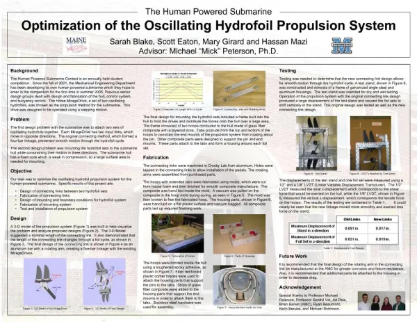
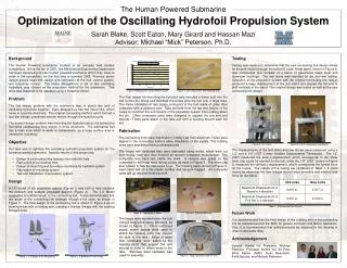
Figure 2: 3-D Model of Final Design Figure 1: 3-D Model of the MirageDrive Figure 9: LVDT’s Attached to Test Stand Figure 8: Test Stand Figure 3: Required Link Length Within a Cycle Figure 6: Parts of Housings Figure 7: Hoops Bonded Inside the Hull Figure 4: Connecting Links with Rotating Arms Figure 5: Fabrication of Hoops z LVDTs x Table 1: Displacement Test Results Tabs Connecting Links End Mounts Input Links Hoops Pin The Human Powered Submarine Optimization of the Oscillating Hydrofoil Propulsion System Sarah Blake, Scott Eaton, Mary Girard and Hassan Mazi Advisor: Michael “Mick” Peterson, Ph.D. • Background • The Human Powered Submarine Contest is an annually held student competition. Since the fall of 2001, the Mechanical Engineering Department has been developing its own human powered submarine which they hope to enter in the competition for the first time in summer 2005. Previous senior design groups dealt with design and fabrication of the hull, control system, and buoyancy control. The Hobie MirageDrive, a set of two oscillating hydrofoils, was chosen as the propulsion method for the submarine. This drive was designed to be operated using a stepping motion. • Problem • The first design problem with the submarine was to attach two sets of oscillating hydrofoils together. Each MirageDrive has two input links, which move in opposite directions. The original connecting method, which formed a four-bar linkage, prevented smooth motion through the hydrofoil cycle. • The second design problem was mounting the hydrofoil sets to the submarine hull while constraining their motion in three directions. The submarine hull has a foam core which is weak in compression, so a large surface area is needed for mounting. • Objective • Our task was to optimize the oscillating hydrofoil propulsion system for the human-powered submarine. Specific results of this project are: • Design of connecting links between two hydrofoil sets • Fabrication of connecting links • Design of mounting and boundary conditions for hydrofoil system • Fabrication of mounting system • Test and installation of propulsion system • Design • A 3-D model of the propulsion system (Figure 1) was built to help visualize the problem and analyze proposed designs (Figure 2). The 3-D Model suggested a nominal length of the connecting link. It also demonstrated that the length of the connecting link changes through a foil cycle, as shown in Figure 3. The final design of the connecting link is shown in Figure 4 as an aluminum bar with a rotating arm, creating a five-bar linkage with the existing MirageDrives. The final design for mounting the hydrofoil sets included a frame built into the hull to hold the drives and distribute the forces onto the hull over a large area. The frame consisted of two hoops contoured to the hull made of glass fiber composite with a plywood core. Tabs protrude from the top and bottom of the hoops to constrain the end mounts of the propulsion system from rotating about the pin. Other composite parts were designed to support the pin and end mounts. These parts attach to the tabs and form a housing around each foil set. Fabrication The connecting links were machined in Crosby Lab from aluminum. Holes were tapped in the connecting links to allow installation of the pedals. The rotating arms were assembled from purchased parts. The hoops with extended tabs were fabricated using molds, which were cut from house foam and then finished for smooth composite manufacture. The composite was hand laid inside the mold. A vacuum was pulled on the composite in the hoop mold during curing, as seen in Figure 5. The mold was then broken to free the fabricated hoop. The housing parts, shown in Figure 6, were hand laid on a flat plastic surface and vacuum bagged. All composite parts laid up required finishing work. Testing Testing was needed to determine that the new connecting link design allows for smooth motion through the hydrofoil cycle. A test stand, shown in Figure 8, was constructed and consists of a frame of galvanized angle steel and aluminum housings. The test stand was intended for dry and wet testing. Operation of the propulsion system with the original connecting link design produced a large displacement of the test stand and caused the foil sets to shift vertically in the stand. This original design was tested as well as the new connecting link design. The displacements of the test stand and one foil set were measured using a 1/2” and a 1/8” LVDT (Linear Variable Displacement Transducer). The 1/2” LVDT measured the axial x-displacement which corresponds to the shear force that would be exerted on the hull, while the 1/8” LVDT, shown in Figure 9, measured the vertical z-displacement which corresponds the tensile force on the hoops. The results of the testing are contained in Table 1. It could clearly be seen that the new linkage moved more smoothly and exerted less force on the stand. Future Work It is recommended that the final design of the rotating arm in the connecting link be manufactured at the AMC for greater corrosion and failure resistance. Also, it is recommended that additional parts be attached to the housing in order to decrease drag. Acknowledgement The hoops were bonded inside the hull using a toughened epoxy adhesive, as shown in Figure 7. Fiber reinforced plastic corner braces were used to attach the housing parts that support the pins to the tabs. Strips of glass fiber composite were added to the housing parts that support the end mounts in order to attach them to the tabs. Stainless steel hardware was used for assembly. Special thanks to Professor Michael Peterson, Professor Senthil Vel, Art Pete, Brian Barker (AMC), Ryan Beaumont, Keith Berube, and Michael Robinson.