Download
1 / 12
140 likes | 398 Views
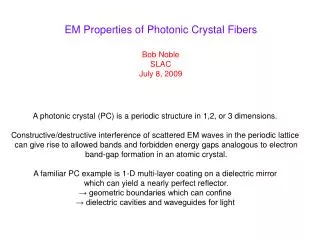
EM Properties of Photonic Crystal Fibers. Bob Noble SLAC July 8, 2009. A photonic crystal (PC) is a periodic structure in 1,2, or 3 dimensions. Constructive/destructive interference of scattered EM waves in the periodic lattice

E N D
EM Properties of Photonic Crystal Fibers Bob Noble SLAC July 8, 2009 A photonic crystal (PC) is a periodic structure in 1,2, or 3 dimensions. Constructive/destructive interference of scattered EM waves in the periodic lattice can give rise to allowed bands and forbidden energy gaps analogous to electron band-gap formation in an atomic crystal. A familiar PC example is 1-D multi-layer coating on a dielectric mirror which can yield a nearly perfect reflector. → geometric boundaries which can confine → dielectric cavities and waveguides for light
Photonic Crystal Fiber (PCF) is 2-D photonic crystal, but uniform in z Photonic Band Gap Fiber Accelerator – Eddie Lin, PRSTAB 4, 051301 (2001) Replace metal boundary by 2-D periodic dielectric (glass with holes) to slow and confine a TM-like accelerating mode within large, central hole or “defect”. Emax/Eacc≈ 2 Dielectric slows down the waves: Mode’s index of refraction n = ck/ω = c/vph ≥ 1
Problem: Field’s magnitude in glass can be much higher than in central hole. Lin found another TM-like accelerating mode with better field ratio in a honey-comb lattice with a more complex defect. Lesson: Tune the defect geometry to adjust the accelerating mode properties.
Mode Competition: Two Types of Defect modes in Hollow-core PBG Fibers “Core defect modes” observed to have Re n<1 (phase vel >c), small Im n (“Telecom”) “Surface defect modes” observed at all values of Re n (any phase vel), larger Im n Accelerating modes for relativistic particles are surface defect modes at n=1, vph=c Outstanding puzzle: Can we design a fiber with a TM-like, core mode with vph>c but arbitrarily close to light line?
Surface defect modes are perturbed lattice modes with frequencies shifted up into the band gap, where they become defect modes. Surface mode counting rule is not a mode number formula but a conservation law: Nlattice + Nsurface = constant. Number of Core Modes in bandgap: Ncore≈ (2πR/λ)2 ∆k/k0 = (R/a)2 (k0a)2 ∆k/k0 For a particle accelerator using a surface mode, we design fiber with no core modes if possible. For telecom, the fiber is designed to eliminate surface modes.
Accelerating Modes in Photonic Band Gap Fibers • Accelerating modes identified as special type of defect mode called “surface modes”: dispersion relation crosses the vphase=c line with high field intensity at defect edge. • Tunable by changing details around the defect boundary. • Core modes nearby in frequency compete for power. • Synchronism and Phase Stability issues over many wavelengths. • Accel. Mode sensitivities vs defect radius R, material index n, and lattice spacing a in the Lin fiber: • dλ/dR = -0.1, (dλ/λ)/(dnmat/nmat) = 2, dλ/da = 1. • Example: For 1% acceleration phase stability over 1000 λ, the relative variation in Lin fiber parameters must be held to: • ΔR/R ~ 10-4, Δnmat/nmat ~ 5×10⁻⁶, Δa/a ~ 10-5
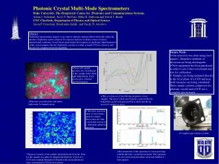
SLAC AARD is working with Incom Inc on Phase 1 SBIR to construct first Lin-type prototype fibers at 2-5 micron wavelengths, to be followed by ~1 micron (Phase 2). Until then, we are using off-the-shelf telecom fibers for first wake-field and input coupler expts on E163 (J. England talk; Cho Ng, Jim Spencer, Johnny Ng posters). These fibers are designed to have good telecom core modes but are not always free of surface modes! Using commercial photonics software (R-Soft BandSolve) and U of Sydney freeware (CUDOS) we found accelerating mode candidates in the HC-1060 fiber (Siemann, Noble, Spencer, Boris Kulmey U of Sydney): Crystal Fibre HC-1060 Fiber Defect ~ 9.5 microns, Lattice period ~ 2.75 microns
epsilon_r BandSolve 10 period X 10 period supercell with central defect (x,z are in units of period a) Lattice dimensions are fine-tuned to give correct band gap diagram. Defect from SEM photo data and is not fine tuned.
HC-1060 bandgap Period a = 2.75 micron 1.01 micron Telecom modes vph>c 1.122 micron SOL accel.-type modes 1.09, 1.08(2), 1.02 microns v=c a After lattice tuned to give correct band gap, all defect modes come out of calculation with no free parameters.
R-Soft BandSolve (Plane Wave Expansion) Simulation: HC-1060 SOL accelerating mode at 1.08 micron in 10X10 supercell: Zc = G2λ2 / Power = 4.93E-03 ohms (terrible! Compare to 19 Ω for Lin mode) Damage Factor = Emax/G = 1.66E+02 (Compare to Lin mode: ~2) Loss Parameter = k1 = G2 /stored energy/length = 1.02E+18 V/C-m (Lin mode: 3.2E21 V/C-m) Group velocity vg= Power flow in y / u = 1.73E8 m/s = 0.807 c (Lin: 0.58c) Mode Losses, 10X10 supercell, 5-layers of holes: Mode Q = 5.88E+03 Loss Coefficient: alpha(1/m) = 1.22E+03 Im neff = 1.05E-04 Power Loss Parameter L (dB/mm) = 5.31E+00 We find a factor of ~7 improvement in confinement per layer of holes added. If we truncate at Layer 8 as in real fiber, we predict Im neff ~ 3E-07, L ~ 1.5 E-02 dB/mm (100 times worse than telecom mode’s power loss).
Summary • Accelerating mode for relativistic particles is a surface defect mode in • the hollow-core PBG fiber with n=1 and vph=c. • PBG fibers support both surface defect modes and core defect • modes. Many modes at the same frequency may compete for input • power. Core modes have vph>c so never synchronous with rel. particle. • 3. Accelerating modes are optimized by varying the details of the surface region • which separates the defect volume and surrounding lattice (Jim Spencer • calculations and design for Incom’s Lin fiber manufacture under SBIR). • 4. Phase stability/synchronization requires constant phase velocity: tight • tolerances on lattice/defect dimensions and material index over mm lengths. • 5. Understanding beam wakefields and input coupling of light to TM • mode is just beginning (Joel England, Johnny Ng, Jim Spencer, Cho Ng) • 5. What is not a problem? Fiber Cooling. For wavelengths <2 micron, loss • in SiO2 is due to Rayleigh scattering <10-6 dB/mm; not absorbed if • cladding is transparent. Diffracted loss dominates. For 8-layer Lin fiber, • diffr. loss is 0.1 dB/mm (G=500 MV/m, 1 psec, 107 Hz, 3.5 mW/mm avg. loss).