1200 kV AC Substation Basic requirements - Example: PGCIL
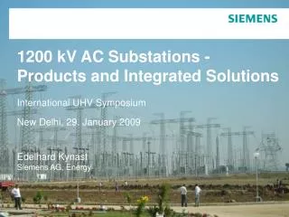
1200 kV AC Substations - Products and Integrated Solutions International UHV Symposium New Delhi, 29. January 2009 Edelhard Kynast Siemens AG, Energy. 1200 kV AC Substation Basic requirements - Example: PGCIL. Electrical Requirements. Rated voltage 1200 kV Rated current, feeder 5000 A

1200 kV AC Substation Basic requirements - Example: PGCIL
E N D
Presentation Transcript
1200 kV AC Substations -Products and Integrated SolutionsInternational UHV SymposiumNew Delhi, 29. January 2009Edelhard KynastSiemens AG, Energy
1200 kV AC SubstationBasic requirements - Example: PGCIL • Electrical Requirements • Rated voltage 1200 kV • Rated current, feeder 5000 A • Rated frequency 50 Hz • Short-circuit current 50 kA / 1 s • Rated lightning impulse withstand voltage 2400 kV • Rated switching impulse withstand voltage 1800 kV • Creepage distance 25 mm/kV (Total 30000 mm) • Environmental conditions • Temperature (min / average / max) +4 ºC / 38 ºC / 50 ºC • Seismic Zone 1 • Wind 47 m/s • Altitude <1000 m
1200 kV AC SubstationBasic requirements - Example: PGCIL • Minimum Clearances • Minimum clearance phase to earth 8300 mm • Minimum clearance phase to phase 11600 mm • (According to draft „IEC 60071-1 Amd.1 Ed. 8.0, 2008-05-16“) • Lowest part of insulation 3500 mm • Min. height lowest live part 18000 mm • Working clearance 18000 mm AIS is PGCIL preferred technology • Assumed distances • Bay distances • Phase to phase distance 20000 mm • Bay width 62000 mm • Three live part levels • Height of lower conductor level 18000 mm • Height of busbar 36000 mm • Height of long spans 55000 mm
1200 kV AC SubstationCircuit Configurations • 1 ½ Breaker Configuration • Arrangement is simple and clear • Acceptable costs • Unrestricted and non-stop operation of all feeders in 2 groups • Busbar maintenance without interruption of power supply • 2 Breaker Configuration Recommended solution: • Double Busbar Configuration more
1200 kV AC SubstationDouble Busbar arrangement - Layout 62,0 m 62,0 m 115,0 m 80,0 m 92,5 m 287,5 m 51,0 m
1200 kV AC SubstationDouble Busbar Arrangement - Layout - Surge Arresters • Disconnectors • Dead Tank Circuit Breakers • Current Transformers • Capacitive Voltage Transformers
1200 kV AC Surge Arresters Development • Based on 800 kV DC-Application • 5 unit surge arrester with grading and corona ring • Active part with four columns in parallel • Additional cooling with aluminum blocks between MO varistors 800 kV DC Design
1200 kV AC Surge Arresters Technical Data • Designation 3EQ5 850-5PT95 • Rated voltage 850 kV • Continuous operating voltage 723 kV • Nominal discharge current 20 kA • Lightning impulse protection level 1700 kV • Switching impulse protection level 1500 kV • Energy discharge capability 55 MJ • Creepage distance 35750 mm • (30 mm/kV) • Height 12 m • Bending moment 150 kNm Voltage-current characteristic of a MO surge arrester for 1200 kV AC power system
1200 kV AC Disconnector - Project Powergrid IndiaRecommendation for Double Side Break Design • Experience in Double Side Break Disconnectors for UHV application • - Double side break ZBF 800 kV AC in service in Ucraine • - Double side break ZBF 515 kV DC in service in China • - Double side break ZBF 824 kV DC installation in China Double Side Break design advantages for 1200 kV AC application - high reliability due to the reduced number of moving parts in the kinematic chain and in the current path - well proven turn and twist design of the current path - space savings in the vertical dimension due to the current path movement only in the horizontal direction
1200 kV AC Disconnector Specified Requirements - Project Powergrid India • Technical parameters 1200 kV AC disconnector & earthing switch • Rated voltage 1200 kV • Frequency 50 Hz • Normal current 6000 Amps • Short time withstand current 50 kA / 1 s • Peak withstand current 125 kA • Lightning impulse withstand voltage • - phase- to- earth 2400 kV • - across isolating distance 2400 kV+685 kV • Switching impulse withstand voltage • - phase- to- earth 1800 kV • - across isolating distance 1800 kV + 980kV • Creepage distance of insulators 25 mm/kV ZBF 824 kV DC, DoubleSideBreak Project Yun Guang, China
UHV - Circuit-Breaker 1200 kV Testing: Short circuit performance • 8DR1-P5-1100 kV – 50 kA • Test at KEMA, Arnhem , February / April 2008 T100a (February 2008) • Full pole test • Time constant 120 ms • Value of last current loop 115 kA • First pole to clear factor 1,3 p. u. • TRV peak value 1600 kV • Minimum arcing time 10,3 ms T10 (April 2008) • Full pole test • First pole to clear factor 1,5 p. u. • TRV peak value 2062 kV • Minimum arcing time 5,1 ms
UHV - Circuit-Breaker 1200 kV Testing: Dielectric performance • 8DR1-P5-1100 kV – 50 kA Prototype • Test at FGH, Manheim , July / August 2008 • Withstand voltage tests • Lightning impulse voltage - phase to earth 2400 kV • - across open cb 2400 + 630 kV • Switching impulse voltage - phase to earth 1800 kV • - across open cb 1675 + 900 kV • Power-frequency voltage - phase to earth 1100 kV • - across open cb 1180 + 320 kV
Current Transformer 1200 kV AC Current TransformersSolutions: SF6 – Free-standing or Ring-core CB-solution • Main parameters • Rated voltage 1200 kV • Rated current 5000 A • Lightning impulse voltage 2400 kV • Switching impulse voltage 1800 kV • Power-frequency voltage 1215 kV • Composite insulators • Creeping distance 25 mm/kV • Overall height 11,3 m • Weight 4.240 kg Ring-core CB-solution
1200 kV AC Capacitive Voltage TransformerRequirements and Technical Data • Main parameters • Rated voltage 1200 kV • Rated current 5000 A • Lightning impulse voltage 2400 kVSwitching impulse voltage 1800 kV • Power-frequency voltage 1200 kV • Capacitance 2000 pF • Creeping distance 25 mm/kV • Overall height 11,6 m • Weight 2450 kg 1100kV CVT Prototype running in Wuhan UHV AC testing base
Solutions for 1200 kV AC SubstationsConclusions • UHV substations are important node-points in the power supply and distribution with a need of high reliability and high availability. • Standards for the UHV level are under consideration, but not available today. • The switchgear systems and equipment presented here for UHV are tailor made to the customers needs. • A simple copying and scaling up from the system levels below is not always possible for the dimensions and parameters, • but the basic knowledge of technologies and designs can be adapted from the experience with 800 kV DC systems and with 800 kV and 1100 kV AC systems.
Thank you, for your attentionInternational UHV SymposiumNew Delhi, 29. January 2009
Circuit Configurations • 2 BB – Double Busbar Configuration • Arrangement is simple and clear • Acceptable costs • Busbar maintance with shut down of the feeders • Unrestricted and non-stop operation of all feeders in 2 groups
Circuit Configurations • 1 ½ Breaker Configuration • Circuit scheme and arrangement not clear • Expensive design • High availability • Selective Fault clearing with interuption of operation, if both busbars under operation
Circuit Configurations • 2 Breaker Configuration • Expensive design • High availability • Selective Fault clearing with interuption of operation