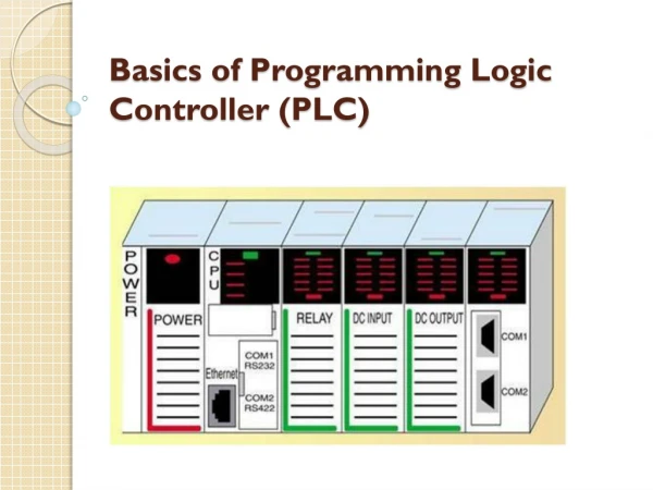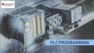
Basics of PLC Programming
690 likes | 741 Views
This course provides an overview of industrial automation focusing on PLC programming basics, history, key components, and future trends. Learn about early automation applications, technology breakthroughs, and current engineering resources.

Basics of PLC Programming
E N D
Presentation Transcript
Basics of PLC Programming EE 100 – Intro to EE Fall 2004 Dr. Stephen Williams, P.E.
Overview • How did we get where we are today? • How does a project at GM in 1968 relate to the work of Henry Leland in the late 1800s? SLC PLC AB GM Ford Autos Sensor Bus Drive
Vocabulary • Programmable Logic Controllers • Definite-purpose computers design to control industrial processes and machines • Drives • Solid-state devices designed to control motors • Sensors • Transducers used to obtain information
First Programmable Controller • General Motors Corporation • Hydromatic Division • Replaced relay-controlled system • PDP-8 minicomputers? • MODICON 084 • Modular Digital Controller
Information Flow Process or Machine Measure Control Programmable Controller
Genesis of Automation • Operation sheets • May date back to the 1830s • Listing of: • All machining operations • The machine tools employed • Tools, jigs, fixtures, and gauges • Organization and flow of work
Industrial Revolution • High-volume production • Interchangeable parts • Transportation system • Inexpensive energy (coal) • Frederick W. Taylor • Scientific management • Henry Ford
Purpose of Automation • Increase productivity • Standardize components or processes • Free workers from repetitive, and sometime dangerous, tasks
Early Automation Applications • 1869 – Refineries in Pennsylvania automatically covert crude oil to kerosene • 1937 – Pictured is the loading and unloading of stators via an overhead conveyor for dipping in continuous process oven
The Case Against Automation • Las Vegas Sun, August 2, 1961 • Jimmy Hoffa saw a new industrial revolution forming with automation being a threat to his giant union more menacing than the Justice Department, Attorney General Bobby Kennedy and the president himself. • He felt he could cope with the Senate committees, the FBI, and all the new legislation being written, which he thinks is aimed at unionism. It is with automation that all his talents, energy and ability must be directed.
Forces Driving Automation • Lower costs • Faster production • Better quality control • How have they remained relevant today?
Engineering Resources • Why do you need all of these engineers running around to make all of this stuff work?
Breakthroughs and Plateaus • Where have we seen breakthroughs, and then plateaus of technology? • Microprocessors • Graphical User Interfaces • Power Electronics • Software Systems
Brief Review of Technology • Traditional (ancient?) devices • Still used in many plants • If it ain’t broke … • Where are we going?
Traditional Relay Logic • Used since … • Control via a series of relay contacts • On and off inputs • Race conditions on the outputs • Very expensive • Hard to design and construct • Difficult to maintain
Traditional Devices • Relays • Contactors • Motor Starters • Manually operated switches • Mechanically operated switches • Electrically operated switches
Relays • Original control elements • Now used as auxiliary devices • The PLC is not designed to switch high currents or voltages
Contactors • Used for heavy-duty switching • Provides isolation from high voltages and large currents • Usefully for large inductive currents, such as motor starting
Motor Starters • Contactors + Overload Relay • Overload relays were usually heaters and bimetal strips • The bimetal strip separates when heated • Next steps: • PLCs and motor starters • Electronic overloads • Intelligent starters
Manually Operated Switches • Pushbuttons • Normally open • Normally closed • Break-then-make • Make-then-break • Selector switches • Maintained or spring return
Mechanically Operated Switches • Limit Switches • Temperature Switches • Pressure Switches • Level Switches
Electrically Operated Switches • Photoelectric Switches • Proximity Switches
What's ahead? • Solid state devices to replace motor starters • Distributed smart sensors • Micro- and nanomachines • Adaptive control • Smart maintenance
Summary • A very brief history of industrial automation • Overview of some of the older technologies • Some thoughts on the future
PLC Systems • CPU • Processor • Memory • One Module • Power Supply • Part of the chassis or a separate module • Programming/ Monitoring Device • I/0 Modules
Input and Output • Input Modules • Convert “real world” signal to PLC input • 24 V, 120 V, Analog, etc. • Output Modules • Convert PLC signal to “real world” output • 24 V, 120 V, Analog, etc. • Limiting values • PLC power supply
Configurations • Fixed I/O • Limited expandability • Rack • Many modules, with the possibility of chaining many racks together • SLC 500 is a fixed I/O device • SLC 5/02 uses a rack configuration
Chassis Versus Rack • One “Rack” is 128 inputs/outputs • A chassis is the outer shell of the PLC • Chassis ≠ Rack • SLC 5/02’s in S-340 have a ten-slot chassis • Slots are numbered from 0 to 9
SLC Image Tables • Hex numbering • Addressing • I1:2.0/01 • I is for the file type • 1 is the file number • 2 is the element number • .0 is the sub-element number (>16) • /01 is the bit number
“Real World” Address • I1:3.0/01 • I is the module type • 1 is redundant • 3 is the slot number • .0 is for terminals above 15 • /01 is the terminal number
Remote Racks • I/O racks located close to the equipment being monitored • Simplifies wiring • Communication modules • Similar to LAN • Fiber Optic • Coaxial cable
Discrete I/O Modules • Either “on” or “off” • Bit oriented • Various ratings • 24 V • 120 V • TTL • 4 – 20 mA
Special I/O Modules • Analog • High speed counter • Thumb-wheel • TTL • Encoder • PID • Servo
Memory Organization • Not the same on all manufactures • Allen Bradley uses two main types • Memory Maps • Data table • User program • Internal registers • Memory allocation could be fixed or variable
RSLogix 500 Screen • Define controller attributes • Model • Memory • Communication • Program files • Main program • Subprograms
RSLogix 500 Screen • Access to input and output tables • Access to timer and control control files
Address Format • What type of device or module • Where is it located physically or in memory • For example, T4:0/DN is the done bit for timer 0 in file 4 • I:2.0 is an input module in slot 2 • Word versus bit addresses • I:3.0 is a word, I:3.0/04 is a bit
Multiword Elements • Timers, counters, and control elements • Three words used • Control word to store status • Preset word to store desired value • Accumulated word to store present value • Control file store a length and position value (on functions other than counters and timers)
RSLogix 500 Screen • Counter C5:0
Program Scan Program Scan • Each cycle through the program and I/O process is called a scan • Scan times vary with the length of the program and the speed of the processor I/O Scan
Programming Environments • Languages available • Ladder logic • Boolean • Function chart • Ladder logic is the most common • Function chart is the future • C, BASIC, etc., are also possible
Transducers • Converts energy from one form to another • Input transducers • Real world into the PLC • Output transducers • PLC to real world
Sensors • Sensors are transducers used to measure or detect • Convert mechanical, magnetic, thermal, or optical variations into electrical quantities • Sensor input is the basis for most of the decisions made in a large system
Proximity Sensors • Detect the presence of a object (target) without physically touching the object • Solid-state devices • Completely encapsulated • Used when: • Detecting small objects • Rapid response is required