Download
1 / 50
530 likes | 773 Views
DEEP DYNAMIC COMPACTION Engr Sarfraz Ali sarfrazengr@yahoo.com. Introduction. Scarcity of suitable construction sites Problem soils Collapsible soils Liquefiable soils Waste materials Wide application Economy. Methods for Soil Improvement. Ground Reinforcement. Ground Improvement.

E N D
DEEP DYNAMIC COMPACTION Engr Sarfraz Ali sarfrazengr@yahoo.com
Introduction • Scarcity of suitable construction sites • Problem soils • Collapsible soils • Liquefiable soils • Waste materials • Wide application • Economy
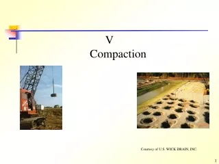
Methods for Soil Improvement Ground Reinforcement Ground Improvement Ground Treatment • Stone Columns • Soil Nails • Deep Soil Nailing • Micropiles (Mini-piles) • Jet Grouting • Ground Anchors • Geosynthetics • Fiber Reinforcement • Lime Columns • Vibro-Concrete Column • Mechanically Stabilized Earth • Biotechnical • Deep Dynamic Compaction • Drainage/Surcharge • Electro-osmosis • Compaction grouting • Blasting • Surface Compaction • Soil Cement • Lime Admixtures • Flyash • Dewatering • Heating/Freezing • Vitrification Compaction
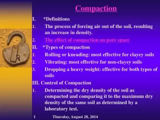
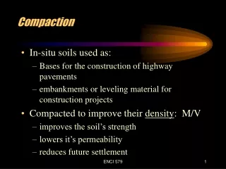
Compaction and Objectives • Compaction • Many types of earth construction, such as dams, retaining walls, highways, and airport, require man-placed soil, or fill. To compact a soil, that is, to place it in a dense state. • The dense state is achieved through the reduction of the air voids in the soil, with little or no reduction in the water content. This process must not be confused with consolidation, in which water is squeezed out under the action of a continuous static load. • Objectives: • Decrease future settlements • Increase shear strength • Decrease permeability
Aim • Share information on: • Experiences of dynamic compaction • Technique • Design • Evaluation • Effectiveness
Sequence • Technique • Energy transfer mechanism • Stages of compaction • Application – which soils are compacted ? • Types • Ground Vibrations • Design Considerations • Questions
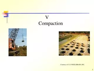
Technique involves repeatedly dropping a large weight from a crane • Weight may range from 6 to 172 tons • Drop height typically varies from 10 m to 40 m
degree of densification achieved is a function of the energy input (weight and drop height) as well as the saturation level, fines content and permeability of the material • 6 – 30 ton weight can densify the loose sands to a depth of 3 m to 12 m
Done systematically in a rectangular or triangular pattern in phases • Each phase can have no of passes; primary, secondary, tertiary, etc.
Spacing between impact points depend upon: • Depth of compressible layer • Permeability of soil • Location of ground water level • Deeper layers are compacted at wider grid spacing, upper layer are compacted with closer grid spacing
Deep craters are formed by tamping • Craters may be filled with sand after each pass • Heave around craters is generally small
Energy transferred by propagation of Rayleigh (surface) waves and volumic (shear and compression) waves • Rayleigh 67 % • Shear 26 % • Compression 7%
Compressibility of saturated soil due to presence of micro bubbles • Gradual transition to liquefaction under repeated impacts • Rapid dissipation of pore pressures due to high permeability after soil fissuring • Thixotropic recovery
Applicable to wide variety of soils • Grouping of soils on the basis of grain sizes
Mainly used to compact granular fills • Particularly useful for compacting rockfills below water and for bouldery soils where other methods can not be applied or are difficult • Waste dumps, sanitary landfills, and mine wastes
In sanitary fills, settlements are caused either by compression of voids or decaying of the trash material over time, DDC is effective in reducing the void ratio, and therefore reducing the immediate and long term settlement. • DDC is also effective in reducing the decaying problem, since collapse means less available oxygen for decaying process. • For recent fills where organic decomposition is still underway, DDC increases the unit weight of the soil mass by collapsing voids and decreasing the void ratio. • For older fills where biological decomposition is complete, DDC has greatest effects by increasing unit weight and reducing long term ground subsidence.
TYPES OF DYNAMIC COMPACTION • Dynamic compaction • Dynamic consolidation • Dynamic replacement • Rotational dynamic compaction • Rapid impact dynamic compaction
Dynamic Compaction • It is the compaction of unsaturated or highly permeable saturated granular materials by heavy tamping • The response to tamping is immediate
Dynamic Consolidation The improvement by heavy tamping of saturated cohesive materials in which the response to tamping is largely time dependent Excess pore water pressures are generated as a result of tamping and dissipate over several hours or days after tamping.
Dynamic Replacement The formation by heavy tamping of large pillars of imported granular soil within the body of soft saturated soil to be improved The original soil is highly compressed and consolidated between the pillars and the excess pore pressure generated requires several hours to dissipate The pillars are used both for soil reinforcement and drainage
Rotational Dynamic Compaction A new dynamic compaction technique which makes use of the free fall energy as well as rotational energy of the tamper called Rotational Dynamic Compaction (RDC) The technique increases depth of improvement in granular soils Comparative study showed that the cone penetration resistance was generally larger than conventional dynamic compaction and the tamper penetration in rotational dynamic compaction was twice as large as that of conventional dynamic compaction
EVALUATION OF IMPROVEMENT W The depth of improvement is proportional to the energy per blow The improvement can be estimated through empirical correlation, at design stage and is verified after compaction through field tests such as Standard Penetration Tests (SPT), Cone Penetration Test (CPT), etc.
Dmax = n√W x H Where, Dmax = Max depth of improvement, m n = Coefficient that caters for soil and equipment variability W = Weight of tamper, tons H = Height of fall of tamper, m The effectiveness of dynamic compaction can also be assessed readily by the crater depth and requirement of backfill
Dynamic compaction generates surface waves with a dominant frequency of 3 to 12 Hz • These vibrations generate compression, shear and Rayleigh waves • The Raleigh waves contain about 67 percent of the total vibration energy and become predominant over other wave types at comparatively small distances from the source • Raleigh waves have the largest practical interest for the design engineers because building foundations are placed near the ground surface
The ground vibrations are quantified in terms of peak particle velocity (PPV); the maximum velocity recorded in any of the three coordinate axes • The measurement of vibrations is necessary to determine any risk to nearby structures • The vibrations can be estimated through empirical correlations or measured with the help of instruments such as portable seismograph, accelerometers, velocity transducers, linear variable displacement transducers (LVDT), etc.
The frequency of the Raleigh waves decreases with increasing distance from the point of impact Relationship between PPV and inverse scaled distance is shown graphically (the inverse scaled distance is the square root of the compaction energy, divided by the distance, d from the impact point)
Tolerance Limits for Structures British Standard 7385: Part 2-1993, lays down following safety limits for various structures having different natural frequencies: • Reinforced or framed structures industrial and heavy commercial buildings at 4 Hz and above 50 mm/s • Un-reinforced or light framed structures residential or light commercial type buildings at 4 Hz –15 Hz 15-20 mm/s • Un-reinforced or light framed residential or light commercial type buildings at 15 Hz –40 Hz and above 20-50 mm/s
Effect on Humans • 0.1 mm/sec not noticeable • 0.15 mm/sec nearly not noticeable • 0.35 mm/sec seldom noticeable • 1.00 mm/sec always noticeable • 2.00 mm/sec clearly noticeable • 6.00 mm/sec strongly noticeable • 14.00 mm/sec very strongly noticeable • 17.8 mm/sec severe noticeable
Depth of improvement, d • Impact energy, E • Influence of cable drag • Equipment limitations • Influence of tamper size • Grid spacing, S • Time delay between passes • Soil conditions
Depth of Improvement Primary concern • Depends on: • Soil conditions • Energy per drop • Contact pressure of tamper • Grid spacing • Number of passes • Time lag between passes
Impact E nergy, E • Weight of tamper times the height of drop • Main parameter in determining the depth of improvement • Can be calculated from the equation Dmax = n√W x H (Free falling of weights)
Influence of Cable Drag • Cable attached to the tamper causes friction and reduces velocity of tamper • Free fall of tamper is more efficient
Equipment limitations • Crane capacity • Height of drop • Mass of tamper • Tamper size
Grid Spacing • Significant effect on depth of improvement • First pass compacts deepest layer, should be equal to the compressible layer • Subsequent passes compact shallower layers, may require lesser energy • Ironing pass compacts top layer
Time Delay between Passes • Allow pore pressures to dissipate • Piezometers can be installed to monitor dissipation of pore pressures following each pass
Grid Spacing • Significant effect on depth of improvement • First pass compacts deepest layer, should be equal to the compressible layer • Subsequent passes compact shallower layers, may require lesser energy • Ironing pass compacts top layer