Download
1 / 28
280 likes | 414 Views
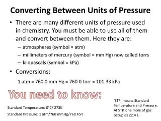
GEMS offers a choice of pressure switches, from compact cylindrical<br>models for OEM use, to larger, enclosed units for rugged process<br>applications. These switches are ideal for the filtering process of<br>coolants in the machine tool industry, use in transmissions of<br>off-highway vehicles and as redundant systems with existing monitors<br>such as transducers.

E N D
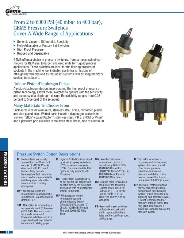
From 2 to 6000 PSI (40 mbar to 400 bar), GEMS Pressure Switches Cover A Wide Range of Applications General, Vacuum, Differential, Specialty Field-Adjustable or Factory Set Switches High Proof Pressure Rugged and Dependable GEMS offers a choice of pressure switches, from compact cylindrical models for OEM use, to larger, enclosed units for rugged process applications. These switches are ideal for the filtering process of coolants in the machine tool industry, use in transmissions of off-highway vehicles and as redundant systems with existing monitors such as transducers. Unique Piston/Diaphragm Design A piston/diaphragm design, incorporating the high proof pressure of piston technology allows these switches to operate with the sensitivity and accuracy of a diaphragm design. Repeatability ranges from 0.25 percent to 5 percent of the set point. Many Materials To Choose From Enclosures include aluminum, stainless steel, brass, reinforced plastic and zinc-plated steel. Wetted parts include a diaphragm available in Buna-n, Teflon® coated Kapton and a pressure port available in stainless steel, brass, zinc or aluminum. ® coated Kapton ® ®, stainless steel, PTFE, EPDM or Viton® Pressure Switch Option Descriptions G: Gold contacts are usually required for low DC current loads (<12 VDC @ 12 mA) associated with TTL input devices. They provide decreased contact resistance, which results in more reliable switching especially in the presence of an oxidizing atmosphere. OXY: Wetted Materials are ultrasonically cleaned per the Compressed Gas Association’s Method G-4.1. PRESSURE SWITCHES R: The restrictor option is recommended for hydraulic systems that need a small reduction in pressure pulsations to increase pressure switch life. It is a pressed in part that has an orifice size of 0.045˝ (1.4 mm) SR: The spiral restrictor option heavily dampens pressure pulsations in any hydraulic system, which prevents false signaling and premature wear. It is not recommended for pressure settings below 1500 psig (103 bar) because it slows the response time of the pressure switch. WM: Weatherpack male termination consists of the following Delphi P/N’s: 12010973 Connector, (12010717 Conn “C” Circuit), 12089040 Male Pins and 12015323 Wire Seals. DE: Deutsch male termination consists of the following Deutsch P/N’s: DT04-2P Connector, (DTO4-3P “C” Circuit) 1060-16-0122 Male Pins and W(2 or 3)P Wedgelok. IP: Ingress Protection is provided by either an epoxy sealed cap (IP65) or silicon wire seals (IP66). On some models, this option is only available with FS option. RB: Rubber Boot is designed to be cut out for the proper wire or cable size by the customer and sealed with an appropriate sealant in the field. WF: Weatherpack female termination consists of the following Delphi P/N’s:(12045793 Conn “C” Circuit), 12089188 Female Pins and 12015323 Wire Seals. 10A: 10A option is provided by a microswitch rated 10 Amperes at 250 VAC. This microswitch has a wide movement differential, which results in a larger deadband than listed in the standard catalog pages. FS: Gems will preset switches to the indicated set point within repeatability limits listed on the specific product catalog page. I-1 Visit www.GemsSensors.com for most current information.
INTRODUCTION Selection Guide Pressure Range Proof Pressure Switch Notes Series Page 0.75 to 15 psi (52 to 1034 mbar) 150 psi (10 bar) PS11 SPST, SPDT — I-3 5 to 150 psi (0.35 to 10 bar) 500 psi (35 bar) Kapton® Diaphragm PS31 I-5 SPST 5 to 100 psi (0.35 to 7 bar) 500 psi (35 bar) PS32 Elastomer Diaphragm I-7 Subminiature Pressure Switches PS51 Kapton® Diaphragm I-5 50 to 300 psi (3.45 to 20 bar) 500 psi (35 bar) SPST PS52 Elastomer Diaphragm I-7 PS61 I-11 15 to 3000 psi (1.03 to 207 bar) 6000 psi (414 bar) SPST — PS62 I-13 5 to 6000 psi (0.35 to 414 bar) 7500 psi (517 bar) SPST, SPDT, DPST, DPDT — PS75 I-19 3.5 to 100 psi (0.24 to 7 bar) 350 psi (24 bar) PS41 SPST, SPDT — I-9 10 to 5000 psi (0.7 to 344 bar) 6000 psi (414 bar) PS71 SPST, SPDT — I-15 Miniature Pressure Switches 10 to 750 psi (0.7 to 52 bar) 3000 psi (207 bar) PS72 SPST, SPDT — I-17 15 to 1750 psi (1 to 121 bar) 4500 psi (517 bar) PS76 SPST, DPDT — I-21 1.5˝ to 15˝ Hg (51 to 508 mbar) 150 psi (10 bar) PS81 SPST, SPDT — I-23 Vacuum Switches 5˝ to 28˝ Hg (169 to 948 mbar) 350 psi (24 bar) PS82 SPST, SPDT — I-25 Solid-State Switches 0 to 6000psi (0 to 400 bar) SPST, Relay or Transistor See Specs PS98 Solid-State I-27 PRESSURE SWITCHES Plastic Diaphragms Option K or Standard Teflon® Coated Kapton® (Polyimide) Diaphragm Elastomer Diaphragms Elastomers offer incredible sensitivity coupled with extremely long life. This results in stable set points over the life of the pressure switch as well as tight deadbands. Their biggest weakness is the increase in modulus (stiffening) that occurs at lower temperatures. This results in pressure switch set points to shift higher and deadbands to increase with decreasing temperature. They also exhibit more hysteresis than Kapton® diaphragms. Option E: EPDM (Ethylene Propylene) Diaphragm. Typically used with phosphate ester based hydraulic fluids, brake fluids, ketones, steam and hot water. Temperature range:-65°F to +212°F (-54°C to +100°C) Option N: Neoprene (Chloroprene) Diaphragm. Typically specified for refrigerant systems. Temperature range: -65°F to +275°F (-54°C to +135°C) Standard: Nitrile (Buna-N). Typically specified on water and petroleum based hydraulic oils. Temperature range: 32°F to 250°F (0°C to 121°C) Option V: Viton® (Fluoroelastomer) Diaphragm. Typically used with alcohols, diesters, solvents, acids and synthetic oils. Also used for high vacuum service.Temperature range: 32°F to 400°F (0°C to 204°C) Teflon® is compatible with almost every liquid and gaseous media. Kapton® has very stable physical properties over a wide temperature range (-100°F to +400°F). This results in pressure switches that exhibit very little set point shift due to temperature extremes. Kapton® possesses exceptional fatigue strength but is very stiff which results in wider but more stable deadbands than most elastomers. I-2 Visit www.GemsSensors.com for most current information.
PS11 – Ultra-Long Life OEM Pressure Switches 0.75 to 15 psi (52 to 1034 mbar) 1,000,000 Cycle Life Typical Factory Set or Adjustable Set Points For low pressure applications, the longevity of our PS11 Series is hard to beat. A life expectancy of 1 million cycles means long-term reliability. Their snap-action microswitch resets automatically and meets or exceeds industry standards. The brass housing offers chemical resistance at an affordable price. Specifications Switch* 5 Amp @ 24 VDC and 250 VAC 1.0 Amp resistive 0.5 Amp inductive @ 24 VDC (-G option) See Table 1 See Table 1 See T Repeatability Wetted Parts Diaphragm Fitting Housing O-Ring Electrical Termination** Proof Pressure Burst Pressure Approvals Weight, Approximate * Gold contacts (option G) may be required for less than 12 VDC and 20 mA. ** Plastic housing is vented to atmosphere. Consult factory for non-vented version. Dimensions Nitrile (optional Viton®, EPDM or Kapton®) Brass Brass Nitrile (optional Viton® or EPDM) DIN 43650A IP00; Terminals IP00; Flying Leads IP00 0 psia to 150 psi (-1 bar to 10.3 bar) 300 psi (20.7 bar) CE, UL Approved units available 0.31 lbs. (0.14 kg) SPDT Shown RED = N.O. GREEN = N.C. BLACK = COMM0N ADJUSTMENT SCREW UNDER CAP Recommended Operating Temperature Limits Diaphragm Material Range Nitrile Viton® 15°F to 250°F (-9°C to +121°C) 0°F to 250°F (-18°C to +121°C) 2˝ (51) EPDM -40°F to +250°F (-40°C to +121°C) -40°F to +250°F (-40°C to +121°C) Kapton® Note: Switches may function below the cold temperature limit but the set point and deadband will increase. Consult factory for details. PRESSURE SWITCHES ø1.75˝ (ø44) 1.10˝ (28) B B DIN 43650A CABLE CLAMP DIN 43650A MALE HALF ONLY 2.34˝ (59) ø1.75˝ (ø44) I-3 Visit www.GemsSensors.com for most current information.
SUbmINIaTURE How To Order Use the Bold characters from the chart below to construct a product code. Please reference Notes. PS11 -10 -4MNB -C -HC -XX -XXXX 1 2 3 4 5 6 1 Pressure Range Code Insert Pressure Range Code from Table 1, below. 2 Pressure Fitting1 -2MNB = 1/8˝ NPTM Brass -4MNB = 1/4˝ NPTM Brass -2FNB = 1/8˝ NPTF Brass -4MGB = 1/4˝ BSPM Brass (G type) -4MSB = 7/16˝-20 SAE Male, Brass -6MSB = 9/16˝-18 SAE Male, Brass 3 Circuit -A = SPST/N.O. -B = SPST/N.C. -C = SPDT 4 Electrical Termination2 -FLXX = Flying Leads3 -ELXX = 1/2˝ Male NPT Conduit w/Flying Leads3 -H = DIN 43650A Male Half Only -HC = DIN 43650A 9mm Cable Clamp -HN = DIN 43650A 1/2˝ NPT Female Conduit 5 Options -OXY = Oxygen Cleaned -WF = Weather Pack Connector, Female -WM = Weather Pack Connector, Male -DE = Deutsch Connector, Male, DT04 Series 6 Fixed Set Point (optional) A. Specify set point -FS (in PSI or mBAR, see example)5 B. Set Point Actuation R on Rising Pressure F on Falling Pressure Example: -FS200MBARF for 200 mBAR Falling or -FS3PSIR for 3 PSI Rising Notes: 1. Other fittings available. Consult factory. 2. DIN units are available with -C SPDT circuit only. 3. 18˝ is standard. Specify lead length in inches (max. 48˝). e.g. -FL18 or -EL30. 4. Ingress Protection requires Fixed Set Point -FS. 5. Set Point must be within Pressure Range selected in Step 1. -V = Viton® Diaphragm -E = EPDM Diaphragm -K = Kapton® Diaphragm -IP = Ingress Protection4 -G = Gold Contacts (for loads less than 12 mA @ 12 VDC) Table 1 — Pressure Range Codes Pressure Range Code Pressure Range Repeatability* Average Deadband** 10 20 0.75-4 psig (51-276 mbar) 3.5-15 psig (241-1034 mbar) ±0.15 psi (10 mbar) +4% of setting ±0.25 psi (17 mbar) +5% of setting 0.2 psi (14 mbar) +9% of setting 0.4 psig (26 mbar) +11% of setting * Repeatability and set point of units may change due to the effects of temperature. ** In certain applications deadband can be tailored and controlled to customer specifications. Consult factory for details. PRESSURE SWITCHES I-4 Visit www.GemsSensors.com for most current information.
PS31/PS51 – Kapton® Diaphragm OEM Subminiature Pressure Switch 5 to 300 psi (0.345 to 20 bar) Ideal for Low Temperature Pneumatic Applications Adjustable or Factory Set These compact pressure switches are designed for OEM applications. Made economical with metal blade contacts in lieu of microswitches, these switches feature Kapton® diaphragms. Kapton® polyimide maintains excellent physical properties over a wide temperature range. It also offers superb chemical resistance and has no known organic solvents. Dimensions The PS31 and PS51 share identical construction and envelope dimensions, with the PS51 Series providing higher pressure ranges. Specifications 0.54˝ (14) HEX HEAD ADJUSTMENT SCREW Operating Temperature Switch* Repeatability Wetted Parts Diaphragm O-Ring Fitting Electrical Termination Deadband Proof Pressure Burst Pressure Approvals Weight, Approximate * Gold contacts (option G) may be required for less than 12 VDC and 20 mA. -40°F to +230°F (-40°C to +110°C) 100 VA Max. See Table 1 15/16˝ AF. (24) Teflon® Coated Kapton® (Solid Teflon® Available) Nitrile (Std.) Consult factory for other materials Brass (optional 316 Stainless Steel) Exposed Terminals IP00; IP option IP66 See Table 1 500 psi (35 bar) 1000 psi (69 bar) CE (limits switch voltage to 42 VDC) Brass: 0.14 lbs. (0.06 kg) 1.120˝ (29) 1.85˝ (47) 0.36˝ (9.07) HEX 15/16˝ (24) 1.58˝ (40.16) 1.51˝ (38.30) PRESSURE PORT ø0.80˝ (ø20) 1/4˝ Spades Flying Leads with IP option PRESSURE SWITCHES I-5 Visit www.GemsSensors.com for most current information.
SUbmINIaTURE How To Order Use the Bold characters from the chart below to construct a product code. Please reference Notes. PS31 -20 -4MNB -A -SP -XX -XXXX 1 2 3 4 5 6 7 1 Series PS31 or PS51 2 Pressure Range Code Insert Pressure Range Code from Table 1, below. 3 Pressure Fitting1 Brass -2MNB = 1/8˝ NPTM -4MNB = 1/4˝ NPTM -2MGB = 1/8˝ BSPM (G type) -4MGB = 1/4˝ BSPM (G type) -8MGB = 1/2˝ BSPM (G type) -M10B = M10 x 1.0, Straight -M12B = M12 x 1.5, Straight -4MSB = 7/16˝-20 SAE Male -6MSB = 9/16˝-18 SAE Male 316 Stainless Steel -2MNS = 1/8˝ NPTM -4MNS = 1/4˝ NPTM -2MGS = 1/8˝ BSPM (G type) -4MGS = 1/4˝ BSPM (G type) -4MSS = 7/16˝-20 SAE Male -6MSS = 9/16˝-18 SAE Male 4 Circuit -A = SPST/N.O. -B = SPST/N.C. 5 Electrical Termination -SP = Spade Terminals (standard) -TS = Terminal Screws -FLXX = Flying Leads2 -FLSXX = Flying Leads w/PVC Shrink Tubing2 -CABXX = 18 AWG PVC Cable3 6 Options -G = Gold Contacts (for loads less than 12 mA @ 12 VDC) -IP = Ingress Protection4 -OXY = Oxygen Cleaned -RB = Rubber Boot (shipped loose) -WF = Weather Pack Connector, Female -WM = Weather Pack Connector, Male -DE = Deutsch Connector, Male, DT04 Series 7 Fixed Set Point (optional) A. Specify set point -FS (in PSI or BAR, see example)5 B. Set Point Actuation R on Rising Pressure F on Falling Pressure Example: -FS0.6BARF for 0.6 BAR Falling or -FS10PSIR for 10 PSI Rising Notes: 1. Other fittings available. Consult factory. 2. 18˝ is standard. Specify lead length in inches (max. 48˝). e.g. -FL18 or -FLS30. 3. 36˝ is minimum. Specify cable length in inches. e.g. -CAB36 or -CAB120. 4. Ingress Protection is available only with -FL, -FLS or -CAB Electrical Termination choices. 5. Set Point must be within Pressure Range selected in Step 2. Table 1 — Pressure Range Codes PS31 Pressure Range Code Pressure Range Repeatability* Average Deadband** 20 30 5-25 psi (0.3-1.7 bar) 20-60 psi (1.4-4.1 bar) ±1 psi (0.07 bar) +3% of setting ±1.5 psi (0.10 bar) +3% of setting 2 psi (0.14 bar) +4% of setting 3 psi (0.21 bar) +4% of setting PRESSURE SWITCHES 40 50-150 psi (3.4-10.3 bar) ±2.5 psi (0.17 bar) +3% of setting 4 psi (0.28 bar) +4% of setting PS51 Pressure Range Code Pressure Range Repeatability* Average Deadband** 15 20 50-150 psi (3.4-10.3 bar) 150-300 psi (10.3-20.7 bar) ±3.0 psi (0.21 bar) +4% of setting ±4 psi (0.28 bar) +4% of setting 5 psi (0.14 bar) +5% of setting 8 psi (0.21 bar) +5% of setting * Repeatability and set point of units may change due to the effects of temperature. ** In certain applications deadband can be tailored and controlled to customer specifications. Consult factory for details. I-6 Visit www.GemsSensors.com for most current information.
PS32/PS52 – Elastomer Diaphragm OEM Subminiature Pressure Switch 5 to 300 psi (0.345 to 20 bar) Ideal for Pneumatic and Low Pressure Hydraulic Applications Adjustable or Factory Set These compact pressure switches are designed for OEM applications. Made economical by using metal blade contacts in lieu of microswitches, the series features long-lasting Elastomer diaphragms in three materials. Elastomer diaphragms offer increased sensitivity and life for applications without temperature extremes. Dimensions The PS32 and PS52 share identical construction and envelope dimensions, with the PS52 Series providing higher pressure ranges. Specifications 0.54˝ (14) Switch* Repeatability Wetted Parts Diaphragm Fitting Electrical Termination Deadband Proof Pressure Burst Pressure Approvals Weight, Approximate * Gold contacts (option G) may be required for less than 12 VDC and 20 mA. 100 VA Max. See Table 1 HEX HEAD ADJUSTMENT SCREW 15/16˝ AF. (24) Elastomer (Nitrile standard) (Viton®, EPDM optional) Brass standard (optional 316 SS) Exposed Terminals IP00; IP option IP66 See Table 1 500 psi (35 bar) 1000 psi (69 bar) CE (limits switch voltage to 42 VDC) Brass: 0.14 lbs. (0.06 kg) 1.120˝ (29) 1.85˝ (47) 0.36˝ (9.07) HEX 15/16˝ (24) 1.58˝ (40.16) 1.51˝ (38.30) PRESSURE PORT Recommended Operating Temperature Limits ø0.80˝ (ø20) Diaphragm Material Range Nitrile Viton® 15°F to 230°F (-9°C to 110°C) 0°F to 230°F (-18°C to 110°C) 1/4˝ Spades Flying Leads with IP option EPDM -40°F to 230°F (-40°C to 110°C) Note: Switches may function below the cold temperature limit but the set points and deadband will increase. Consult factory for details. PRESSURE SWITCHES I-7 Visit www.GemsSensors.com for most current information.
SUbmINIaTURE How To Order Use the Bold characters from the chart below to construct a product code. Please reference Notes. PS32 -20 -4MNB -A -SP -XX -XXXX 1 2 3 4 5 6 7 1 Series PS32 or PS52 2 Pressure Range Code Insert Pressure Range Code from Tables 1, below. 3 Pressure Fitting1 Brass -2MNB = 1/8˝ NPTM -4MNB = 1/4˝ NPTM -2MGB = 1/8˝ BSPM (G type) -4MGB = 1/4˝ BSPM (G type) -4MSB = 7/16˝-20 SAE Male 316 Stainless Steel -2MNS = 1/8˝ NPTM -4MNS = 1/4˝ NPTM -2MGS = 1/8˝ BSPM (G type) -4MGS = 1/4˝ BSPM (G type) -4MSS = 7/16˝-20 SAE Male 4 Circuit -A = SPST/N.O. -B = SPST/N.C. 5 Electrical Termination -SP = Spade Terminals (standard) -TS = Terminal Screws -FLXX = Flying Leads2 -FLSXX = Flying Leads w/PVC Shrink Tubing2 -CABXX = 18 AWG PVC Cable3 6 Options -OXY = Oxygen Cleaned -RB = Rubber Boot (shipped loose) -WF = Weather Pack Connector, Female -WM = Weather Pack Connector, Male -DE = Deutsch Connector, Male, DT04 Series 7 Fixed Set Point (optional) A. Specify set point -FS (in PSI or BAR, see example)5 B. Set Point Actuation R on Rising Pressure F on Falling Pressure Example: -FS0.6BARF for 0.6 BAR Falling or -FS10PSIR for 10 PSI Rising Notes: 1. Other fittings available. Consult factory. 2. 18˝ is standard. Specify lead length in inches (max. 48˝). e.g. -FL18 or -FLS30. 3. 36˝ is minimum. Specify cable length in inches. e.g. -CAB36 or -CAB120. 4. Ingress Protection is available only with -FL, -FLS or -CAB Electrical Termination choices. 5. Set Point must be within Pressure Range selected in Step 2. -V = Viton® Diaphragm -E = EPDM Diaphragm -H = ECOH Diaphragm -G = Gold Contacts (for loads less than 12 mA @ 12 VDC) -IP = Ingress Protection4 Table 1 — Pressure Range Codes PS32 PRESSURE SWITCHES Pressure Range Code Pressure Range Repeatability* Average Deadband** 20 30 5-25 psi (0.3-1.7 bar) 20-60 psi (1.4-4.1 bar) ±1 psi (0.07 bar) +3% of setting ±1.5 psi (0.10 bar) +3% of setting 2 psi (0.14 bar) +4% of setting 3 psi (0.21 bar) +4% of setting 40 50-150 psi (3.4-10.3 bar) ±2.5 psi (0.17 bar) +3% of setting 4 psig (0.28 bar) +4% of setting PS52 Pressure Range Code Pressure Range Repeatability* Average Deadband** 15 20 50-150 psi (3.4-10.3 bar) 150-300 psi (10.3-20.7 bar) ±3.0 psi (0.21 bar) +4% of setting ±4 psi (0.28 bar) +4% of setting 5 psi (0.14 bar) +5% of setting 8 psi (0.21 bar) +5% of setting * Repeatability and set point of units may change due to the effects of temperature. ** In certain applications deadband can be tailored and controlled to customer specifications. Consult factory for details. I-8 Visit www.GemsSensors.com for most current information.
PS41 – Economical Miniature Pressure Switches 3.5 to 100 psi (0.24 to 7 bar) These miniature pressure switches are designed for demanding applications where space and/or price are strong concerns. The switches utilize a piston/diaphragm design, which incorporates the high proof pressure of piston technology with the sensitivity of diaphragm designs. Switches are field adjustable via an Allen head screw that is hidden to protect against unauthorized tampering. Dimensions Specifications Switch Repeatability Wetted Parts Diaphragm Material Fitting Electrical Termination SPST; SPDT See Table 1 ø1.10˝ (ø28) FLYING LEAD 3/32˝ or 1/8˝ ALLEN WRENCH ADJUSTMENT SCREW Nitrile (optional EPDM, Viton® or Neoprene) Brass (optional 316 Stainless Steel) DIN 43650A IP65; Terminals IP00; Flying Leads IP65; Option IP: IP66; Conduit with Flying Leads IP65 350 psi (24 bar) 700 psi (48 bar) CE, UL Approved units available Brass: 0.3 lbs. (0.14 kg) 1.58˝ (40) PRESSURE PORT RED, NO. GREEN, NC. BLACK, COM. Proof Pressure Burst Pressure Approvals Weight, Approximate INGRESS PROTECTION OPTION (IP66) WITH FLYING LEADS FACTORY SET ONLY ø1.25˝ (ø32) Recommended Operating Temperature Limits Options Selected 2.20˝ (56) No option, -10A, -SP or -RD 15°F to 185°F (-9°C to +85°C) 0°F to 185°F (-18°C to +85°C) -10°F to +185°F (-23°C to +85°C) -10°F to +185°F (-23°C to +85°C) Diaphragm Material -RD or -RD and -G -SP or -10A 15°F to 250°F (-9°C to +121°C) 0°F to 250°F (-18°C to +121°C) -10°F to +250°F (-23°C to +121°C) -10°F to +250°F (-23°C to +121°C) 15°F to 212°F (-9°C to +100°C) 0°F to 212°F (-18°C to +100°C) -10°F to +212°F (-23°C to +100°C) -10°F to +212°F (-23°C to +100°C) Nitrile 1.10˝ (28) DIN 43650A – MALE HALF ONLY Viton® EPDM Neoprene DIN 43650A 1.95˝ (50) Note: Switches may function below the cold temperature limit but the set points and deadband will increase. Consult factory for details. PRESSURE SWITCHES RIGHT ANGLE DIN (HNR) Electrical Switch Ratings ADJUSTMENT SCREW UNDER CAP SCREW Options Selected AC DC 5 amps resistive, 3 amps inductive @ 28 Volts 1 amp resistive, 0.5 amp inductive @ 28 Volts — No option or -RD 5 amps @ 125/250 Volts -G or -RD with -G 1 amp @ 125 Volts PRESSURE PORT DIN 43650-HNR -SP without -G 10.1 amps @ 125/250 Volts -SP with -G 2 amps @ 125/250 Volts — B 2.80˝ (71) 1.78˝ (45) 2.14˝ (54) 1.12˝ AF (28) I-9 Visit www.GemsSensors.com for most current information.
mINIaTURE How To Order Use the Bold characters from the chart below to construct a product code. Please reference Notes. PS41 -10 -4MNB -C -H -XX -XXXX 1 2 3 4 5 6 1 Pressure Range Code Insert Pressure Range Code from Table 1, below. 2 Pressure Fitting1 Brass -2MNB = 1/8˝ NPTM -4MNB = 1/4˝ NPTM -2MGB = 1/8˝ BSPM (G type) -4MGB = 1/4˝ BSPM (G type) -4MSB = 7/16˝-20 SAE Male -6MSB = 9/16˝-18 SAE Male 316 Stainless Steel -2MNS = 1/8˝ NPTM -4MNS = 1/4˝ NPTM -4MGS = 1/4˝ BSPM (G type) -4MSS = 7/16˝-20 SAE Male 3 Circuit -A = SPST/N.O. -B = SPST/N.C. -C = SPDT 4 Electrical Termination -SP = Spade Terminals2 -FLXX = Flying Leads3 -FLSXX = Flying Leads w/PVC Shrink Tubing3 -ELXX = 1/2˝ NPT Male Conduit w/Flying Leads4 -CABXX = 18 AWG PVC Cable5 -H = DIN 43650A Male Half Only6 -HR = Right Angle DIN 43650A Male Half Only6 -HC = DIN 43650A 9mm Cable Clamp6 -HCR = Right Angle DIN 43650A 9mm Cable Clamp6 -HN = DIN 43650A with 1/2˝ Female NPT Conduit6 -HNR = Right Angle DIN 43650A with 1/2˝ Female NPT Conduit6 5 Options7 -10A = 10A @ 125/250 VAC Max. Rating -G = Gold Contacts (for loads less than 12 mA @ 12 VDC) -RD = Reduced Differential (25% reduction typical) -IP = Ingress Protection8 -OXY = Oxygen Cleaned -WF = Weather Pack Connector, Female -WM = Weather Pack Connector, Male -DE = Deutsch Connector, Male, DT04 Series 6 Fixed Set Point (optional) A. Specify set point -FS (in PSI or BAR, see example)9 B. Set Point Actuation R on Rising Pressure F on Falling Pressure Example: -FS0.5BARF for 0.5 BAR Falling or -FS5PSIR for 5 PSI Rising Notes: 1. Other fittings available. Consult factory. 2. Requires -10A or -G option. (20% increase in deadband typical) 3. 18˝ is standard. Specify lead length in inches (max. 48˝). e.g. -FL18 or -FLS30. 4. 18˝ is standard. Specify lead length in inches (max. 48˝). e.g. -EL18 or -EL30. 5. 36˝ is minimum. Specify cable length in inches. e.g. -CAB36 or -CAB120. 6. DIN connectors require -C SPDT circuit. 7. Options -10A, -G or -RD cannot be combined. 8. Ingress Protection is available only with -FL, -FLS or -CAB Electrical Termination choices. Ingress Protection requires Fixed Set Point -FS. 9. Set Point must be within Pressure Range selected in Step 1. -V = Viton® Diaphragm -N = Neoprene Diaphragm -E = EPDM Diaphragm PRESSURE SWITCHES Table 1 — Pressure Range Codes Pressure Range Code Pressure Range Repeatability* Average Deadband** 10 20 3.5-8 psi (0.24-0.55 bar) 7-30 psi (0.48-2.07 bar) ±0.35 psi (0.024 bar) +2% of setting ±0.8 psi (0.055 bar) +2% of setting 1.50 psi (0.14 bar) +7% of setting 3 psi (0.21 bar) +8% of setting 30 25-100 psi (1.7-6.9 bar) ±2.0 psi (0.138 bar) +2% of setting 5 psig (0.28 bar) +10% of setting * Repeatability and set point of units may change due to the effects of temperature. ** These numbers are for the standard microswitch. With either the -SP or -10A option, the values are typically 20% greater than those listed. With the -RD option, the values will be typically 25% less than those listed. In certain applications deadband can be tailored and controlled to customer specifications. Consult factory for details. I-10 Visit www.GemsSensors.com for most current information.
PS61 – OEM Subminiature Pressure Switch 15 to 3000 psi (1 to 207 bar) Exceptional Size-to-Pressure-Range Ratio Adjustable or Factory Set Perfect for Demanding OHV Applications These compact pressure switches are designed for OEM applications. They are equipped with high proof pressure capabilities for demanding hydraulic applications such as forklifts, scissor lifts, and off road equipment. Specifications Dimensions Switch* Repeatability Wetted Parts Diaphragm Fitting Electrical Termination Deadband Proof Pressure Burst Pressure Approvals Weight, Approximate * Gold contacts (option G) may be required for less than 12 VDC and 20 mA. 100 VA Max. See Table 1 See Table 1 See T 0.54˝ (14) 15/16˝ AF (24) Nitrile (optional Neoprene, EPDM or Viton®) Zinc-Plated Steel (optional 316 Stainless Steel) Exposed Terminals IP00; IP option IP66 See Table 1 6000 psi (414 bar) 9000 psi (600 bar) CE (limits switch voltage to 42 VDC) Steel: 0.14 lbs. (0.06 kg) ADJUSTMENT SCREW IP67 CAP 1.10˝ (28) 1.93˝ (49) 0.36˝ (9) 1.68˝ (43) Recommended Operating Temperature Limits Diaphragm Material Range Nitrile Viton® 15°F to 230°F (-9°C to +110°C) 0°F to 230°F (-18°C to +110°C) EPDM -40°F to +230°F (-40°C to +110°C) 1/4˝ Spades Flying Leads with IP option Note: Switches may function below the cold temperature limit but the set points and deadband will increase. Consult factory for details. PRESSURE SWITCHES I-11 Visit www.GemsSensors.com for most current information.
SUbmINIaTURE How To Order Use the Bold characters from the chart below to construct a product code. Please reference Notes. PS61 -11 -4MNZ -A -SP -XX -XXXX 1 2 3 4 5 6 1 Pressure Range Code Insert Pressure Range Code from Table 1, below. 2 Pressure Fitting1 12L14 Zinc-Plated Steel -2MNZ = 1/8˝ NPTM 12L14 -4MNZ = 1/4˝ NPTM 12L14 -2MGZ = 1/8˝ BSPM 12L14 (G type) -4MGZ = 1/4˝ BSPM 12L14 (G type) -4MSZ = 7/16˝-20 SAE Male -6MSZ = 9/16˝-18 SAE Male -8MSZ = 3/4˝-16 SAE Male -M10Z = M10 x 1.0, Straight -M12Z = M12 x 1.5, Straight 316 Stainless Steel -2MNS = 1/8˝ NPTM -4MNS = 1/4˝ NPTM -2MGS = 1/8˝ BSPM (G type) -4MGS = 1/4˝ BSPM (G type) -4MSS = 7/16˝-20 SAE Male -6MSS = 9/16˝-18 SAE Male 3 Circuit -A = SPST/N.O. -B = SPST/N.C. 4 Electrical Termination -SP = Spade Terminals (standard) -TS = Terminal Screws -FLXX = Flying Leads2 -FLSXX = Flying Leads w/PVC Shrink Tubing2 -CABXX = 18 AWG PVC Cable3 5 Options -OXY = Oxygen Cleaned (requires SS housing) -RB = Rubber Boot (shipped loose) -WF = Weather Pack Connector, Female -WM = Weather Pack Connector, Male -DE = Deutsch Connector, Male, DT04 Series 6 Fixed Set Point (optional) A. Specify set point -FS (in PSI or BAR, see example)6 B. Set Point Actuation R on Rising Pressure F on Falling Pressure Example: -FS3BARF for 3 BAR Falling or -FS60PSIR for 60 PSI Rising Notes: 1. Other fittings available. Consult factory. 2. 18˝ is standard. Specify lead length in inches (max. 48˝). e.g. -FL18 or -FLS30. 3. 36˝ is minimum. Specify cable length in inches. e.g. -CAB36 or -CAB120. 4. Ingress Protection is available only with -FL, -FLS or -CAB Electrical Termination choices. 5. -SR will result in wider deadbands and slower response times. 6. Set Point must be within Pressure Range selected in Step 1. -V = Viton® Diaphragm -E = EPDM Diaphragm -N = Neoprene Diaphragm -H = ECOH Diaphragm -G = Gold Contacts (for loads less than 12 mA @ 12 VDC) -IP = Ingress Protection4 -R = Restrictor (low damping coefficient) Brass -SR = Spiral Restrictor (high damping coefficient) 12L14 Steel w/Black Oxide Finish5 PRESSURE SWITCHES Table 1 — Pressure Range Codes Pressure Range Code Pressure Range Repeatability* Average Deadband** 11 15 15-60 psi (1-4 bar) 40-150 psi (3-10 bar) ±1.5 psi (0.10 bar) +3% of setting ±2.5 psi (0.17 bar) +3% of setting 3 psi (0.21 bar) +5% of setting 5 psig (0.34 bar) +6% of setting 19 75-275 psi (5.2-18.9 bar) ±3.75 psi (0.26 bar) +3% of setting 7 psig (0.48 bar) +8% of setting 25 150-500 psi (10.3-34.5 bar) ±5 psi (0.34 bar) +3% of setting 10 psi (0.69 bar) +10% of setting 29 275-800 psi (19.0-55.2 bar) ±8 psi (0.55 bar) +3% of setting 15 psi (1.03 bar) +11% of setting 35 400-1100 psi (27.6-76 bar) ±13 psi (0.90 bar) +3% of setting 30 psi (2.07 bar) +12% of setting 50 1000-3000 psi (69-207 bar) ±35 psi (2.41 bar) +3% of setting 70 psi (4.83 bar) +14% of setting * Repeatability and set point of units may change due to the effects of temperature. ** In certain applications deadband can be tailored and controlled to customer specifications. Consult factory for details. I-12 Visit www.GemsSensors.com for most current information.
PS62 – OEM Subminiature Pressure Switch New! New! 15 to 600 psi (1 to 41 bar) Exceptional Size-to-Pressure-Range Ratio Adjustable or Factory Set Minimal Set Point Change at Low Temperature Extremes These compact pressure switches are designed for medium pressure OEM applications. They offer all the performance of our proven PS61 model with the low temperature capability of Kapton®. Dimensions Specifications 0.54˝ (14) Operating Temperature Switch* Repeatability Wetted Parts Housing Diaphragm O-Ring Electrical Termination Deadband Proof Pressure Burst Pressure Approvals Weight, Approximate * Gold contacts (option G) may be required for less than 12 VDC and 20 mA. -40°F to +230°F (-40°C to +110°C) 100 VA Max. See Table 1 See Table 1 See T 15/16˝ AF (24) ADJUSTMENT SCREW Zinc-Plated Steel (optional 316L Stainless Steel) Kapton® (polyimide) Nitrile (other materials available) Exposed Terminals IP00; IP option IP66 See Table 1 3000 psi (207 bar) 6000 psi (414 bar) CE (limits switch voltage to 42 VDC) Steel: 0.14 lbs. (0.06 kg) IP67 CAP 1.10˝ (28) 1.93˝ (49) 0.36˝ (9) 1.68˝ (43) 1/4˝ Spades Flying Leads with IP option PRESSURE SWITCHES I-13 Visit www.GemsSensors.com for most current information.
SUbmINIaTURE How To Order Use the Bold characters from the chart below to construct a product code. Please reference Notes. PS62 -10 -4MNZ -A -SP -XX -XXXX 1 2 3 4 5 6 1 Pressure Range Code Insert Pressure Range Code from Table 1, below. 2 Pressure Fitting1 12L14 Zinc-Plated Steel -2MNZ = 1/8˝ NPTM 12L14 -4MNZ = 1/4˝ NPTM 12L14 -2MGZ = 1/8˝ BSPM 12L14 (G type) -4MGZ = 1/4˝ BSPM 12L14 (G type) -4MSZ = 7/16˝-20 SAE Male -6MSZ = 9/16˝-18 SAE Male 316L Stainless Steel -2MNS = 1/8˝ NPTM -4MNS = 1/4˝ NPTM -2MGS = 1/8˝ BSPM (G type) -4MGS = 1/4˝ BSPM (G type) -4MSS = 7/16˝-20 SAE Male -6MSS = 9/16˝-18 SAE Male 3 Circuit -A = SPST/N.O. -B = SPST/N.C. 4 Electrical Termination -SP = Spade Terminals (standard) -TS = Terminal Screws -FLXX = Flying Leads2 -FLSXX = Flying Leads w/PVC Shrink Tubing2 -CABXX = 18 AWG PVC Cable3 5 Options -OXY = Oxygen Cleaned -RB = Rubber Boot (shipped loose) -WF = Weather Pack Connector, Female -WM = Weather Pack Connector, Male -DE = Deutsch Connector, Male, DT04 Series 6 Fixed Set Point (optional) A. Specify set point -FS (in PSI or BAR, see example)6 B. Set Point Actuation R on Rising Pressure F on Falling Pressure Example: -FS3BARF for 3 BAR Falling or -FS60PSIR for 60 PSI Rising Notes: 1. Other fittings available. Consult factory. 2. 18˝ is standard. Specify lead length in inches (max. 48˝). e.g. -FL18 or -FLS30. 3. 36˝ is minimum. Specify cable length in inches. e.g. -CAB36 or -CAB120. 4. Ingress Protection is available only with -FL, -FLS or -CAB Electrical Termination choices. 5. -SR will result in wider deadbands and lower response time. 6. Set Point must be within Pressure Range selected in Step 1. -N = Neoprene Diaphragm -G = Gold Contacts (for loads less than 12 mA @ 12 VDC) -IP = Ingress Protection4 -R = Restrictor (low damping coefficient) Brass -SR = Spiral Restrictor (high damping coefficient) 12L14 Steel w/Black Oxide Finish5 Table 1 — Pressure Range Codes Pressure Range Code Pressure Range Repeatability* Average Deadband** PRESSURE SWITCHES 10 20 15-60 psi (1-4 bar) 40-150 psi (3-10 bar) ±1.5 psi (0.10 bar) +4% of setting ±2.5 psi (0.17 bar) +4% of setting 3 psi (0.21 bar) +6% of setting 5 psig (0.34 bar) +7% of setting 30 75-275 psi (5.2-18.9 bar) ±3.75 psi (0.26 bar) +4% of setting 7 psig (0.48 bar) +9% of setting 40 150-600 psi (10.3-41.4 bar) ±5 psi (0.34 bar) +4% of setting 10 psi (0.69 bar) +11% of setting * Repeatability and set point of units may change due to the effects of temperature. ** In certain applications deadband can be tailored and controlled to customer specifications. Consult factory for details. I-14 Visit www.GemsSensors.com for most current information.
PS71 – General Purpose Mini Pressure Switches 10 to 5000 psi (0.7 to 344 bar) These versatile general purpose switches with snap action microswitches can be used in a wide range of hydraulic and pneumatic applications. Their proven piston/ diaphragm design offers outstanding accuracy over a very wide pressure range with an outstanding 6000 psi proof pressure. Their modular construction allows Gems to offer a large number of standard pressure fittings in two materials as well as numerous electrical ratings and terminations. Users can easily configure this model to numerous electrical ratings and terminations. Users can easily configure this model to meet their needs. Specifications Dimensions Switch Repeatability Wetted Parts Diaphragm Fitting Electrical Termination SPST; SPDT See Table 1 DIN 43650A WITH CABLE CLAMP Nitrile (optional EPDM, Viton® or Neoprene) Zinc-Plated Steel (Optional 316 SS) DIN 43650A IP65; Spade Terminals IP00; Flying Leads IP65; Conduit with Flying Leads IP65; IP option IP66 6000 psi (414 bar) 9000 psi (600 bar) CE, UL Approved units available 0.4 lbs. (0.15 kg) B B 2.20˝ (56) Proof Pressure Burst Pressure Approvals Weight, Approximate 2.87˝ (73) SPDT Shown FLYING LEAD VERSION ADJUSTMENT SCREW Recommended Operating Temperature Limits Options Selected 1.84˝ (47) No option, -10A, -SP or -RD 15°F to 185°F (-9°C to +85°C) 0°F to 185°F (-18°C to +85°C) -10°F to +185°F (-23°C to +85°C) -10°F to +185°F (-23°C to +85°C) Diaphragm Material -RD or -RD and -G -SP or -10A RED, NO. GREEN, NC. BLACK, COM. 15°F to 250°F (-9°C to +121°C) 0°F to 250°F (-18°C to +121°C) -10°F to +250°F (-23°C to +121°C) -10°F to +250°F (-23°C to +121°C) 15°F to 212°F (-9°C to +100°C) 0°F to 212°F (-18°C to +100°C) -10°F to +212°F (-23°C to +100°C) -10°F to +212°F (-23°C to +100°C) Nitrile Viton® IP66 OPTION ø1.25˝ (ø32) EPDM Neoprene 2.45˝ (62) PRESSURE SWITCHES Note: Switches may function below the cold temperature limit but the set points and deadband will increase. Consult factory for details. Electrical Switch Ratings RIGHT ANGLE DIN 43650A WITH CABLE CLAMP Options Selected AC DC 5 amps resistive, 3 amps inductive @ 28 Volts 1 amp resistive, 0.5 amp inductive @ 28 Volts — No option or -RD 5 amps @ 125/250 Volts OPTIONAL PORT THREAD SIZES SEE ORDERING DATA -G only or -RD with -G 1 amp @ 125 Volts -10A only or -SP without -G 10.1 amps @ 125/250 Volts -SP with -G 2 amps @ 125/250 Volts — 2.80˝ (71) 1.75˝ (38) 2.36˝ (60) 1-1/8˝ AF (28) ADJUSTMENT SCREW UNDER CAP SCREW I-15 Visit www.GemsSensors.com for most current information.
mINIaTURE How To Order Use the Bold characters from the chart below to construct a product code. Please reference Notes. PS71 -10 -4MNZ -C -H -XX -XXXX 1 2 3 4 5 6 1 Pressure Range Code Insert Pressure Range Code from Table 1, below. 2 Pressure Fitting1 12L14 Zinc-Plated Steel -2MNZ = 1/8˝ NPTM -4MNZ = 1/4˝ NPTM -2MGZ = 1/8˝ BSPM (G type) -4MGZ = 1/4˝ BSPM (G type) -4MSZ = 7/16˝-20 SAE Male -6MSZ = 9/16˝-18 SAE Male 316 Stainless Steel -2MGS = 1/8˝ BSPM (G type) -4MNS = 1/4˝ NPTM -4MGS = 1/4˝ BSPM (G type) 3 Circuit -A = SPST/N.O. -B = SPST/N.C. -C = SPDT 4 Electrical Termination -SP = Spade Terminals2 -FLXX = Flying Leads3 -FLSXX = Flying Leads w/PVC Shrink Tubing3 -ELXX = 1/2˝ NPT Male Conduit w/Flying Leads4 -CABXX = 18 AWG PVC Cable5 -H = DIN 43650A Male Half Only6 -HR = Right Angle DIN 43650A Male Half Only6 -HC = DIN 43650A 9mm Cable Clamp6 -HCR = Right Angle DIN 43650A 9mm Cable Clamp6 -HN = DIN 43650A with 1/2˝ Female NPT Conduit6 -HNR = Right Angle DIN 43650A with 1/2˝ Female NPT Conduit6 5 Options7 -10A = 10A @ 125/250 VAC Max. Rating -G = Gold Contacts (for loads less than 12 mA @ 12 VDC) -RD = Reduced Differential (25% reduction typical) -IP = Ingress Protection8 -OXY = Oxygen Cleaned9 -R = Restrictor (low damping coefficient) Brass -SR = Spiral Restrictor (high damping coefficient) 300 Series Stainless Steel10 -WF = Weather Pack Connector, Female -WM = Weather Pack Connector, Male -DE = Deutsch Connector, Male, DT04 Series 6 Fixed Set Point (optional) A. Specify set point -FS (in PSI or BAR, see example)11 B. Set Point Actuation R on Rising Pressure F on Falling Pressure Example: -FS2BARF for 2 BAR Falling or -FS20PSIR for 20 PSI Rising Notes: 1. Other fittings available. Consult factory. 2. 20% increase in deadband typical. 3. 18˝ is standard. Specify lead length in inches (max. 48˝). e.g. -FL18 or -FLS30. 4. 18˝ is standard. Specify lead length in inches (max. 48˝). e.g. -EL18 or -EL30. 5. 36˝ is minimum. Specify cable length in inches. e.g. -CAB36 or -CAB120. 6. DIN connectors require -C SPDT circuit. 7. Options -10A, -G or -RD cannot be combined. 8. Ingress Protection is available only with -FL, -FLS or -CAB Electrical Termination choices. Ingress Protection requires Fixed Set Point -FS. 9. Requires stainless steel housing. 10. -SR will result in wider deadbands and slower response time. 11. Set Point must be within Pressure Range selected in Step 1. -V = Viton® Diaphragm -E = EPDM Diaphragm -N = Neoprene Diaphragm PRESSURE SWITCHES Table 1 — Pressure Range Codes Pressure Range Code Pressure Range Repeatability* Average Deadband** 10 20 10-30 psi (0.7-2.1 bar) 25-75 psi (1.7-5.2 bar) ±1.5 psi (0.103 bar) +2% of setting ±2.5 psi (0.172 bar) +2% of setting 3.5 psi (0.28 bar) +11% of setting 3.5 psi (0.28 bar) +11% of setting 30 65-300 psi (4.5-20.7 bar) ±5.0 psi (0.345 bar) +2% of setting 20 psig (1.38 bar) +11% of setting 40 250-1000 psi (17.2-69.0 bar) ±15 psi (1.03 bar) +2% of setting 45 psig (3.10 bar) +12% of setting 50 1000-3000 psi (69-206.8 bar) ±30 psi (2.06 bar) +3% of setting 70 psig (4.83 bar) +12% of setting 60 2500-5000 psi (172.4-344.7 bar) ±50 psi (3.45 bar) +4% of setting 140 psi (9.65 bar) +13% of setting * Repeatability and set point of units may change due to the effects of temperature. ** These numbers are for the standard microswitch. With either the -SP or -10A option, the values are typically 20% greater than those listed. With the -RD option, the values will be typically 25% less than those listed. In certain applications deadband can be tailored and controlled to customer specifications. Consult factory for details. I-16 Visit www.GemsSensors.com for most current information.
PS72 – General Purpose Mini Pressure Switches New! New! 10 to 750 psi (0.7 to 51.7 bar) Adjustable or Factory Set Minimal Set Point Change at Low Temperature Extremes These versatile microswitch based pressure switches are designed for medium pressure OEM applications. They offer all the performance of our proven PS71 model with the low temperature capability of Kapton®. Specifications Switch Repeatability Wetted Parts Housing Diaphragm O-Ring Electrical Termination SPST; SPDT See Table 1 Dimensions DIN 43650A WITH CABLE CLAMP Zinc-Plated Steel (316L stainless steel and brass available) Kapton® (polyimide) Nitrile (other materials available) DIN 43650A IP65; Spade Terminals IP00; Flying Leads IP65; Conduit with Flying Leads IP65; IP option IP66 3000 psi (207 bar) 6000 psi (414 bar) CE, UL Approved units available Steel: 0.4 lbs. (0.15 kg) B B 2.20˝ (56) Proof Pressure Burst Pressure Approvals Weight, Approximate 2.87˝ (73) SPDT Shown FLYING LEAD VERSION ADJUSTMENT SCREW Recommended Operating Temperature Limits Options Selected Temperature -RD No Options -40°F to +250°F (-40°C to +121°C) -40°F to +185°F (-40°C to +85°C) 1.84˝ (47) RED, NO. GREEN, NC. BLACK, COM. -SP or -10A -40°F to +212°F (-40°C to +100°C) Electrical Switch Ratings IP66 OPTION ø1.25˝ (ø32) Options Selected AC DC 5 amps resistive, 3 amps inductive @ 28 Volts 1 amp resistive, 0.5 amp inductive @ 28 Volts — No option or -RD 5 amps @ 125/250 Volts 2.45˝ (62) -G only or -RD with -G 1 amp @ 125 Volts PRESSURE SWITCHES -10A only or -SP without -G 10.1 amps @ 125/250 Volts -SP with -G 2 amps @ 125/250 Volts — RIGHT ANGLE DIN 43650A WITH CABLE CLAMP OPTIONAL PORT THREAD SIZES SEE ORDERING DATA 2.80˝ (71) 1.75˝ (38) 2.36˝ (60) 1-1/8˝ AF (28) ADJUSTMENT SCREW UNDER CAP SCREW I-17 Visit www.GemsSensors.com for most current information.
mINIaTURE How To Order Use the Bold characters from the chart below to construct a product code. Please reference Notes. PS72 -10 -4MNZ -C -H -XX -XXXX 1 2 3 4 5 6 1 Pressure Range Code Insert Pressure Range Code from Table 1, below. 2 Pressure Fitting1 12L14 Zinc-Plated Steel -2MNZ = 1/8˝ NPTM -4MNZ = 1/4˝ NPTM -2MGZ = 1/8˝ BSPM (G type) -4MGZ = 1/4˝ BSPM (G type) -4MSZ = 7/16˝-20 SAE Male -6MSZ = 9/16˝-18 SAE Male 316 Stainless Steel -2MGS = 1/8˝ BSPM (G type) -4MNS = 1/4˝ NPTM -4MGS = 1/4˝ BSPM (G type) 3 Circuit -A = SPST/N.O. -B = SPST/N.C. -C = SPDT 4 Electrical Termination -SP = Spade Terminals2 -FLXX = Flying Leads3 -FLSXX = Flying Leads w/PVC Shrink Tubing3 -ELXX = 1/2˝ NPT Male Conduit w/Flying Leads4 -CABXX = 18 AWG PVC Cable5 -H = DIN 43650A Male Half Only6 -HR = Right Angle DIN 43650A Male Half Only6 -HC = DIN 43650A 9mm Cable Clamp6 -HCR = Right Angle DIN 43650A 9mm Cable Clamp6 -HN = DIN 43650A with 1/2˝ Female NPT Conduit6 -HNR = Right Angle DIN 43650A with 1/2˝ Female NPT Conduit6 5 Options7 -10A = 10A @ 125/250 VAC Max. Rating -G = Gold Contacts (for loads less than 12 mA @ 12 VDC) -RD = Reduced Differential (25% reduction typical) -IP = Ingress Protection8 -OXY = Oxygen Cleaned9 -R = Restrictor (low damping coefficient) Brass -SR = Spiral Restrictor (high damping coefficient) 300 Series Stainless Steel10 -WF = Weather Pack Connector, Female -WM = Weather Pack Connector, Male -DE = Deutsch Connector, Male, DT04 Series 6 Fixed Set Point (optional) A. Specify set point -FS (in PSI or BAR, see example)11 B. Set Point Actuation R on Rising Pressure F on Falling Pressure Example: -FS2BARF for 2 BAR Falling or -FS20PSIR for 20 PSI Rising Notes: 1. Other fittings available. Consult factory. 2. Requires -10A or -G option. (20% increase in deadband typical) 3. 18˝ is standard. Specify lead length in inches (max. 48˝). e.g. -FL18 or -FLS30. 4. 18˝ is standard. Specify lead length in inches (max. 48˝). e.g. -EL18 or -EL30. 5. 36˝ is minimum. Specify cable length in inches. e.g. -CAB36 or -CAB120. 6. DIN connectors require -C SPDT circuit. 7. Options -10A, -G or -RD cannot be combined. 8. Ingress Protection is available only with -FL, -FLS or -CAB Electrical Termination choices. Ingress Protection requires Fixed Set Point -FS. 9. Requires stainless steel housing. 10. -SR will result in wider deadbands and slower response times. 11. Set Point must be within Pressure Range selected in Step 1. PRESSURE SWITCHES Table 1 — Pressure Range Codes Pressure Range Code Pressure Range Repeatability Average Deadband* 10 20 10-30 psi (0.7-2.1 bar) 25-75 psi (1.7-5.2 bar) ±1.5 psi (0.103 bar) +3% of setting ±2.5 psi (0.172 bar) +3% of setting 3.5 psi (0.28 bar) +12% of setting 3.5 psi (0.28 bar) +12% of setting 30 65-300 psi (4.5-20.7 bar) ±5.0 psi (0.345 bar) +3% of setting 20 psig (1.38 bar) +12% of setting 40 250-750 psi (17.2-51.7 bar) ±15 psi (1.03 bar) +3% of setting 45 psig (3.10 bar) +13% of setting * These numbers are for the standard microswitch. With either the -SP or -10A option, the values are typically 20% greater than those listed. With the -RD option, the values will be typically 25% less than those listed. In certain applications deadband can be tailored and controlled to customer specifications. Consult factory for details. I-18 Visit www.GemsSensors.com for most current information.
PS75 – Rugged Cylindrical Pressure Switch Side Mounted DIN Connection Top Mounted Electrical Connection 5 to 6000 psi (0.35 to 414 bar) Wear Disc Design for Longer Life DPDT Models Available Gems PS75 Series have all metal surfaces for overload stops and deliver reliable operation under extremely high pressure surges. They are designed with a wear disc and cushioning ring for increased life. The switches use a piston/diaphragm design, which combine the high proof pressure of piston technology with the sensitivity of a diaphragm design. They can be field or factory adjusted. Dimensions Specifications PRESSURE PORT DIN 43650A – RIGHT ANGLE WITH CABLE CLAMP Switch Repeatability Wetted Parts Diaphragm Fitting Housing Electrical Termination SPST; SPDT; DPST; DPDT See Table 1 B B 2.79˝ (71) Nitrile (optional Viton®, Neoprene or EPDM) Zinc-Plated Steel (optional 316 Stainless Steel) Brass or Zinc-Plated Steel (optional 316 Stainless Steel) DIN 43650A IP65; Conduit with Flying Leads IP65; Flying Leads IP65 7500 psi (517 bar) except range 10: 500 psi (35 bar) 9000 psi (600 bar) CE, UL Approved units available Steel: 0.6 lbs. (0.27 kg) 1.781˝ (45) 2.348˝ (60) ø1.185˝ (ø30) 1˝ HEX (25.4) ADJUSTMENT SCREW UNDER CAP Proof Pressure Burst Pressure Approvals Weight, Approximate 2.70˝ (69) 1.00˝ (25.4) Recommended Operating Temperature Limits ø1.12˝ (ø28) Circuit Codes ø1.19˝ (ø30) -AA, -BB, -CC Diaphragm Material -A, -B, -C (or -A, -B, -C with -RD option) 15°F to 250°F (-9°C to +121°C) 0°F to 250°F (-18°C to +121°C) 1/8˝ NPT THREAD PRESSURE PORT Nitrile (Std) Viton® 15°F to 185°F (-9°C to +85°C) 0°F to 185°F (-18°C to +85°C) EPDM -10°F to +185°F (-23°C to +85°C) -10°F to +250°F (-23°C to +121°C) 2.31˝ (58.6) 2.76˝ (70) Neoprene -10°F to +185°F (-23°C to +85°C) -10°F to +250°F (-23°C to +121°C) PRESSURE SWITCHES Note: Switches may function below the cold temperature limit but the set points and deadband will increase. Consult factory for details. Electrical Switch Ratings RED=N.O. BLACK=COMMON GREEN=N.C. STD. 18˝ WIRE LENGTH Circuit Code AC DC ø1.19˝ ø1.19˝ (ø30) 5 amps resistive, 3 amps inductive @ 28 Volts 1 amp resistive, 0.5 amp inductive @ 28 Volts 2 switches rated 5 amps resistive, 3 amps inductive @ 28 Volts 2 switches rated 1 amp resistive, 0.5 amp inductive @ 28 Volts -A, -B, -C1 5 amps @ 125/250 Volts -A, -B, -C2 1 amp @ 125 Volts ADJUSTMENT SCREW 2 switches rated 5 amps @ 125/250 Volts 2 switches rated 1 amp @ 125/250 Volts -AA, -BB, -CC1 SPDT DPST -AA, -BB, -CC2 Notes: 1. Without Gold Contacts Option (-G). 2. With Gold Contacts Option (-G). I-19 Visit www.GemsSensors.com for most current information.
mINIaTURE How To Order Use the Bold characters from the chart below to construct a product code. Please reference Notes. PS75 -10 -4MNZ -C -H -XX -XXXX 1 2 3 4 5 6 1 Pressure Range Code Insert Pressure Range Code from Table 1, below. 2 Pressure Fitting1 12L14 Zinc-Plated Steel -2MNZ = 1/8˝ NPTM -4MNZ = 1/4˝ NPTM -4FNZ = 1/4˝ NPTF -4MGZ = 1/4˝ BSPM (G type) -4FGZ = 1/4˝ BSPF (G type) -4MSZ = 7/16˝-20 SAE Male -6MSZ = 9/16˝-18 SAE Male -4SSZ = 7/16˝-20 SAE Male Swivel 316 Stainless Steel -4MNS = 1/4˝ NPTM -4MGS = 1/4˝ BSPM (G type) -4FGS = 1/4˝ BSPF (G type) -6MSS = 9/16˝-18 SAE Male 3 Circuit -A = SPST/N.O. -B = SPST/N.C. -C = SPDT -AA = DPST/N.O.2 -BB = DPST/N.C.2 -CC = DPDT2 4 Electrical Termination -FLXX = Flying Leads3 -ELXX = 1/2˝ NPT Male Conduit w/Flying Leads4 -H = DIN 43650A Male Half Only5 -HR = Right Angle DIN 43650A Male Half Only5 -HC = DIN 43650A 9mm Cable Clamp5 -HCR = Right Angle DIN 43650A 9mm Cable Clamp5 -HN = DIN 43650A with 1/2˝ Female NPT Conduit5 -HNR = Right Angle DIN 43650A with 1/2˝ Female NPT Conduit5 5 Options -V = Viton® Diaphragm -N = Neoprene Diaphragm -E = EPDM Diaphragm -G = Gold Contacts (for loads less than 12 mA @ 12 VDC) -RD = Reduced Differential (25% reduction typical) -OXY = Oxygen Cleaned6 -R = Restrictor (low damping coefficient) Brass -SR = Spiral Restrictor (high damping coefficient) 300 Series Stainless Steel7 -WF = Weather Pack Connector, Female -WM = Weather Pack Connector, Male -DE = Deutsch Connector, Male, DT04 Series 6 Fixed Set Point (optional) A. Specify set point -FS (in PSI or BAR, see example)8 B. Set Point Actuation R on Rising Pressure F on Falling Pressure Example: -FS1BARF for 1 BAR Falling or -FS20PSIR for 20 PSI Rising Notes: 1. Manifold mounts available. Consult factory. 2. Requires -FL or -EL electrical termination. 3. 18˝ is standard. Specify lead length in inches (max. 48˝). e.g. -FL18 or -FL30. 4. 18˝ is standard. Specify lead length in inches (max. 48˝). e.g. -EL18 or -EL30. 5. DIN connectors require -C SPDT circuit. 6. Requires stainless steel pressure fitting. 7. -SR will result in wider deadbands and slower response times. 8. Set Point must be within Pressure Range selected in Step 1. Table 1 — Pressure Range Codes For Circuit Codes -A, -B and -C Pressure Range Code Pressure Range Repeatability* Average Deadband** 10 20 5-25 psi (0.35-1.7 bar) 15-75 psi (1.0-5.2 bar) ±1.0 psi (0.07 bar) +2% of setting ±2.5 psi (0.17 bar) +2% of setting 3 psi (0.21 bar) +5% of setting 5 psig (0.34 bar) +10% of setting PRESSURE SWITCHES 30 50-150 psi (3.5-10.3 bar) ±6 psi (0.41 bar) +2% of setting 15 psig (1.03 bar) +13% of setting 40 150-650 psi (10.3-44.8 bar) ±15 psi (1.03 bar) +2% of setting 25 psi (1.72 bar) +14% of setting 50 500-1750 psi (34.5-121 bar) ±25 psi (1.72 bar) +2% of setting 55 psi (3.79 bar) +15% of setting 60 1000-3500 psi (69-241 bar) ±45 psi (3.10 bar) +3% of setting 100 psi (6.89 bar) +16% of setting 70 2500-6000 psi (172-414 bar) ±80 psi (5.51 bar) +4% of setting 200 psi (13.8 bar) +17% of setting For Circuit Codes -AA, -BB and -CC*** Pressure Range Code Pressure Range Repeatability* Average Deadband** 10 20 5-25 psi (0.35-1.7 bar) 15-75 psi (1.0-5.2 bar) ±1.5 psi (0.10 bar) +3% of setting ±3.5 psi (0.24 bar) +3% of setting 2 psi (0.14 bar) +5% of setting 4 psig (0.28 bar) +8% of setting 30 50-150 psi (3.5-10.3 bar) ±9 psi (0.62 bar) +3% of setting 13 psig (0.90 bar) +10% of setting 40 150-650 psi (10.3-44.8 bar) ±22 psi (1.51 bar) +3% of setting 21 psi (1.45 bar) +11% of setting 50 500-1750 psi (34.5-121 bar) ±35 psi (2.41 bar) +3% of setting 45 psi (3.10 bar) +12% of setting 60 1000-3500 psi (69-241 bar) ±60 psi (4.14 bar) +4% of setting 80 psi (5.52 bar) +13% of setting 70 2500-6000 psi (172-414 bar) ±100 psi (6.89 bar) +5% of setting 160 psi (11.0 bar) +14% of setting * Repeatability and set point of units may change due to the effects of temperature. ** In certain applications deadband can be tailored and controlled to customer specifications. Consult factory for details. *** Operation of both switches in most cases will not be simultaneous but will occur within the specifications listed. Deadband figures already reflect the improvement from the -RD option which is automatically included in the -AA, -BB and -CC circuits. I-20 Visit www.GemsSensors.com for most current information.
PS76 – Rugged Cylindrical Pressure Switch New! New! Side Mounted DIN Connection Top Mounted Electrical Connection 15 to 1750 psi (1 to 121 bar) Minimal Set Point Change at Low Temperature Extremes DPDT Models Available These versatile microswitch based pressure switches are designed for high pressure OEM applications. They offer all the performance of our proven PS75 model with the low temperature capability of Kapton®. Dimensions Specifications Switch Repeatability Wetted Parts Port Fitting Diaphragm O-Ring Electrical Termination SPST; SPDT; DPST; DPDT See Table 1 PRESSURE PORT DIN 43650A – RIGHT ANGLE WITH CABLE CLAMP Zinc-Plated Steel (316L Stainless Steel available) Kapton® (polyimide) Nitrile (other materials available) DIN 43650A IP65; Conduit with Flying Leads IP65; Flying Leads IP65 4500 psi (517 bar) except Range 10: 500 psi (35 bar) 6000 psi (414 bar) CE, UL Approved units available Steel: 0.6 lbs. (0.27 kg) B B 2.79˝ (71) 1.781˝ (45) Proof Pressure Burst Pressure Approvals Weight, Approximate 2.348˝ (60) ø1.185˝ (ø30) 1˝ HEX (25.4) ADJUSTMENT SCREW UNDER CAP 2.70˝ (69) Recommended Operating Temperature Limits 1.00˝ (25.4) Circuit Codes -AA, -BB, -CC ø1.12˝ (ø28) Diaphragm Material -A, -B, -C (or -A, -B, -C with -RD option) ø1.19˝ (ø30) Teflon® Coated Kapton®-40°F to +185°F (-40°C to +85°C) -40°F to +250°F (-40°C to +121°C) 1/8˝ NPT THREAD PRESSURE PORT Electrical Switch Ratings Circuit Code AC DC 2.31˝ (58.6) 2.76˝ (70) 5 amps resistive, 3 amps inductive @ 28 Volts 1 amp resistive, 0.5 amp inductive @ 28 Volts 2 switches rated 5 amps resistive, 3 amps inductive @ 28 Volts 2 switches rated 1 amp resistive, 0.5 amp inductive @ 28 Volts -A, -B, -C1 5 amps @ 125/250 Volts PRESSURE SWITCHES -A, -B, -C2 1 amp @ 125 Volts 2 switches rated 5 amps @ 125/250 Volts 2 switches rated 1 amp @ 125/250 Volts -AA, -BB, -CC1 RED=N.O. BLACK=COMMON GREEN=N.C. STD. 18˝ WIRE LENGTH -AA, -BB, -CC2 ø1.19˝ ø1.19˝ (ø30) Notes: 1. Without Gold Contacts Option (-G). 2. With Gold Contacts Option (-G). ADJUSTMENT SCREW SPDT DPST I-21 Visit www.GemsSensors.com for most current information.
mINIaTURE How To Order Use the Bold characters from the chart below to construct a product code. Please reference Notes. PS76 -10 -4MNZ -C -H -XX -XXXX 1 2 3 4 5 6 1 Pressure Range Code Insert Pressure Range Code from Table 1, below. 2 Pressure Fitting1 12L14 Zinc-Plated Steel -2MNZ = 1/8˝ NPTM -4MNZ = 1/4˝ NPTM -4FNZ = 1/4˝ NPTF -4MGZ = 1/4˝ BSPM (G type) -4FGZ = 1/4˝ BSPF (G type) -4MSZ = 7/16˝-20 SAE Male -6MSZ = 9/16˝-18 SAE Male -4SSZ = 7/16˝-20 SAE Male Swivel 316L Stainless Steel -4MNS = 1/4˝ NPTM -4MGS = 1/4˝ BSPM (G type) -4FGS = 1/4˝ BSPF (G type) -6MSS = 9/16˝-18 SAE Male 3 Circuit -A = SPST/N.O. -B = SPST/N.C. -C = SPDT -AA = DPST/N.O.2 -BB = DPST/N.C.2 -CC = DPDT2 4 Electrical Termination -FLXX = Flying Leads3 -ELXX = 1/2˝ NPT Male Conduit w/Flying Leads4 -H = DIN 43650A Male Half Only5 -HR = Right Angle DIN 43650A Male Half Only5 -HC = DIN 43650A 9mm Cable Clamp5 -HCR = Right Angle DIN 43650A 9mm Cable Clamp5 -HN = DIN 43650A with 1/2˝ Female NPT Conduit5 -HNR = Right Angle DIN 43650A with 1/2˝ Female NPT Conduit5 5 Options -G = Gold Contacts (for loads less than 12 mA @ 12 VDC) -RD = Reduced Differential (25% reduction typical) -OXY = Oxygen Cleaned6 -R = Restrictor (low damping coefficient) Brass -SR = Spiral Restrictor (high damping coefficient) 300 Series Stainless Steel7 -WF = Weather Pack Connector, Female -WM = Weather Pack Connector, Male -DE = Deutsch Connector, Male, DT04 Series 6 Fixed Set Point (optional) A. Specify set point -FS (in PSI or BAR, see example)8 B. Set Point Actuation R on Rising Pressure F on Falling Pressure Example: -FS1BARF for 1 BAR Falling or -FS20PSIR for 20 PSI Rising Notes: 1. Manifold mounts available. Consult factory. 2. Requires -FL or -EL electrical termination. 3. 18˝ is standard. Specify lead length in inches (max. 48˝). e.g. -FL18 or -FL30. 4. 18˝ is standard. Specify lead length in inches (max. 48˝). e.g. -EL18 or -EL30. 5. DIN connectors require -C SPDT circuit. 6. Requires stainless steel pressure fitting. 7. -SR will result in wider deadbands and slower response times. 8. Set Point must be within Pressure Range selected in Step 1. Table 1 — Pressure Range Codes PRESSURE SWITCHES For Circuit Codes -A, -B and -C Pressure Range Code Pressure Range Repeatability* Average Deadband** 10 20 15-75 psi (1.0-5.2 bar) 50-150 psi (3.5-10.3 bar) ±2.5 psi (0.17 bar) +3% of setting ±6 psi (0.41 bar) +3% of setting 5 psig (0.34 bar) +11% of setting 15 psig (1.03 bar) +14% of setting 30 150-650 psi (10.3-44.8 bar) ±15 psi (1.03 bar) +3% of setting 25 psi (1.72 bar) +15% of setting 40 500-1750 psi (34.5-121 bar) ±25 psi (1.72 bar) +3% of setting 55 psi (3.79 bar) +16% of setting For Circuit Codes -AA, -BB and -CC*** Pressure Range Code Pressure Range Repeatability* Average Deadband** 10 20 15-75 psi (1.0-5.2 bar) 50-150 psi (3.5-10.3 bar) ±3.5 psi (0.24 bar) +4% of setting ±9 psi (0.62 bar) +4% of setting 4 psig (0.28 bar) +9% of setting 13 psig (0.90 bar) +11% of setting 30 150-650 psi (10.3-44.8 bar) ±22 psi (1.51 bar) +4% of setting 21 psi (1.45 bar) +12% of setting 40 500-1750 psi (34.5-121 bar) ±35 psi (2.41 bar) +4% of setting 45 psi (3.10 bar) +13% of setting ** In certain applications deadband can be tailored and controlled to customer specifications. Consult factory for details. *** Operation of both switches in most cases will not be simultaneous but will occur within the specifications listed. Deadband figures already reflect the improvement from the -RD option which is automatically included in the -AA, -BB and -CC circuits. * Repeatability and set point of units may change due to the effects of temperature. I-22 Visit www.GemsSensors.com for most current information.
PS81 – Ultra-Long Life Vacuum Switches 1.5˝ to 15˝ Hg (51 to 508 mbar) Sensitive Diaphragm for Lower Set Points Factory Fixed or Adjustable Set Points For low vacuum applications, the longevity of our PS81 Series is hard to beat. A life expectancy of 1 million cycles means long-term reliability. Their brass housing and choice of four diaphragm materials ensures chemical compatibility with your system. PS81 series switches have a field adjustable set point or can be factory set. Specifications Switch* 5A @ 125/250 VAC, 3 Amp inductive @ 24 VDC (Std) See Table 1 See Table 1 See T Repeatability Wetted Parts Diaphragm and O-Ring Fitting Housing Spring Spring Guide Electrical Termination** Dimensions Nitrile standard (optional EPDM, Viton® or Kapton® with o-ring) Brass Brass 300 Series SS Delrin® DIN 43650A IP00; Terminals IP00; Flying Leads IP00; IP option IP00 0 psia to 150 psig (-1 bar to 10.3 bar) 500 psi (34.5 bar) CE, UL Approved units available 0.31 lbs. (0.14 kg) SPDT Shown Flying Leads RED = N.O. GREEN = N.C. BLACK = COMM0N ADJUSTMENT SCREW UNDER CAP Proof Pressure Burst Pressure Approvals Weight, Approximate * Gold contacts (option G) may be required for less than 12 VDC and 20 mA. ** Plastic housing is vented to atmosphere. Consult factory for sealed versions. Recommended Operating Temperature Limits 2.150˝ (55) Diaphragm Material Range Nitrile Viton® 15°F to 250°F (-9°C to +121°C) 0°F to 250°F (-18°C to +121°C) ø1.86˝ (ø47) EPDM -40°F to +250°F (-40°C to +121°C) -40°F to +250°F (-40°C to +121°C) Kapton® Note: Switches may function below the cold temperature limit but the set points and deadband will increase. Consult factory for details. DIN 43650A – with Cable Clamp 1.10˝ (28) PRESSURE SWITCHES B B DIN 43650A DIN 43650A – Male Half Only 2.34˝ (59) I-23 Visit www.GemsSensors.com for most current information.
vaCUUm SWITCHES How To Order Use the Bold characters from the chart below to construct a product code. Please reference Notes. PS81 -10 -4MNB -C -H -XX -XXXX 1 2 3 4 5 6 1 Pressure Range Code Insert Pressure Range Code from Table 1, below. 2 Pressure Fitting -2MNB = 1/8˝ NPTM Brass -4MNB = 1/4˝ NPTM Brass -2FNB = 1/8˝ NPTF Brass -4MGB = 1/4˝ BSPM Brass (G type) -4MSB = 7/16˝-20 SAE Male, Brass -6MSB = 9/16˝-18 SAE Male, Brass 3 Circuit -A = SPST/N.O. -B = SPST/N.C. -C = SPDT 4 Electrical Termination -FLXX = Flying Leads1 -ELXX = 1/2˝ NPT Male Conduit w/Flying Leads2 -H = DIN 43650A Male Half Only3 -HC = DIN 43650A 9mm Cable Clamp3 -HN = DIN 43650A with 1/2˝ Female NPT Conduit3 5 Options -OXY = Oxygen Cleaned -IP = Ingress Protection4 6 Fixed Set Point (optional) A. Specify set point -FS (in Inches Hg or mBAR, see example)5 B. Set Point Actuation R on Rising Vacuum F on Falling Vacuum Example: -FS100MBARF for 100 mBAR Falling or -FS2INHGR for 2˝ Hg Rising Notes: 1. 18˝ is standard. Specify lead length in inches (max. 48˝). e.g. -FL18 or -FL30. 2. 18˝ is standard. Specify lead length in inches (max. 48˝). e.g. -EL18 or -EL30. 3. DIN connectors require -C SPDT circuit. 4. Ingress Protection is available only with -FL or -EL Electrical Termination and requires Fixed Set Point -FS. 5. Set Point must be within Pressure Range selected in Step 1. -V = Viton® Diaphragm -E = EPDM Diaphragm -K = Kapton® Diaphragm (Nitrile O-ring) -G = Gold Contacts (for loads less than 12 mA @ 12 VDC) Table 1 — Pressure Range Codes Pressure Range Code Pressure Range Repeatability* Average Deadband** 10 20 1.5-5” Hg (51-169 mbar) 4-15” Hg (136-508 mbar) ±0.2” Hg (7 mbar) +3% of setting ±0.35” Hg (12 mbar) +4% of setting 0.3” Hg (10 mbar) +9% of setting 0.6” Hg (20 mbar) +11% of setting * Repeatability and set point of units may change due to the effects of temperature. ** In certain applications deadband can be tailored and controlled to customer specifications. Consult factory for details. PRESSURE SWITCHES I-24 Visit www.GemsSensors.com for most current information.
PS82 – Economical Miniature Vacuum Switches 5˝ to 28˝ Hg (169 to 948 mbar) These miniature vacuum switches, based on our proven PS71 series, are designed for demanding applications where space and/or price are strong concerns. Specifications Switch Repeatability Wetted Parts Diaphragm Material Fitting Spring Electrical Termination SPST; SPDT See Table 1 Nitrile standard (optional EPDM, Viton® and Neoprene) Brass (optional 316 Stainless Steel) 316 Stainless Steel DIN 43650A IP65; Male Conduit with Flying Leads IP65; Flying Leads IP00; IP option IP66 0 psia to 350 psig (-1 bar to 24 bar) 700 psi (48 bar) CE Brass: 0.4 lbs. (0.18 kg) Dimensions SPDT Shown ø1.10˝ (ø28) FLYING LEAD 3/32˝ or 1/8˝ ALLEN WRENCH ADJUSTMENT SCREW Proof Pressure Burst Pressure Approvals Weight, Approximate 1.58˝ (40) PRESSURE PORT RED, NO. GREEN, NC. BLACK, COM. Recommended Operating Temperature Limits Options Selected INGRESS PROTECTION OPTION (IP66) WITH FLYING LEADS FACTORY SET ONLY ø1.25˝ (ø32) No option, -10A, -SP or -RD 15°F to 185°F (-9°C to +85°C) 0°F to 185°F (-18°C to +85°C) -10°F to +185°F (-23°C to +85°C) -10°F to +185°F (-23°C to +85°C) Diaphragm Material -RD or -RD and -G -SP or -10A 15°F to 250°F (-9°C to +121°C) 0°F to 250°F (-18°C to +121°C) -10°F to +250°F (-23°C to +121°C) -10°F to +250°F (-23°C to +121°C) 15°F to 212°F (-9°C to +100°C) 0°F to 212°F (-18°C to +100°C) -10°F to +212°F (-23°C to +100°C) -10°F to +212°F (-23°C to +100°C) Nitrile Viton® 2.20˝ (56) EPDM Neoprene 1.10˝ (28) DIN 43650A – MALE HALF ONLY Note: Switches may function below the cold temperature limit but the set points and deadband will increase. Consult factory for details. Electrical Switch Ratings PRESSURE SWITCHES DIN 43650A 1.95˝ (50) Options Selected AC DC 5 amps resistive, 3 amps inductive @ 28 Volts 1 amp resistive, 0.5 amp inductive @ 28 Volts — No option or -RD 5 amps @ 125/250 Volts with cable clamp -G only or -RD with -G 1 amp @ 125 Volts -10A only or -SP without -G 10.1 amps @ 125/250 Volts -SP with -G 2 amps @ 125/250 Volts — I-25 Visit www.GemsSensors.com for most current information.
vaCUUm SWITCHES How To Order Use the Bold characters from the chart below to construct a product code. Please reference Notes. PS82 -10 -4MNB -C -H -XX -XXXX 1 2 3 4 5 6 1 Pressure Range Code Insert Pressure Range Code from Table 1, below. 2 Pressure Fitting1 Brass -2MNB = 1/8˝ NPTM -4MNB = 1/4˝ NPTM -2MGB = 1/8˝ BSPM (G type) -4MGB = 1/4˝ BSPM (G type) -4MSB = 7/16˝-20 SAE Male -6MSB = 9/16˝-18 SAE Male 316 Stainless Steel -2MNS = 1/8˝ NPTM -4MNS = 1/4˝ NPTM -4MGS = 1/4˝ BSPM (G type) 3 Circuit -A = SPST/N.O. -B = SPST/N.C. -C = SPDT 4 Electrical Termination -FLXX = Flying Leads2 -FLSXX = Flying Leads w/PVC Shrink Tubing2 -ELXX = 1/2˝ NPT Male Conduit w/Flying Leads3 -CABXX = 18 AWG PVC Cable4 -H = DIN 43650A Male Half Only5 -HR = Right Angle DIN 43650A Male Half Only5 -HC = DIN 43650A 9mm Cable Clamp5 -HCR = Right Angle DIN 43650A 9mm Cable Clamp5 -HN = DIN 43650A with 1/2˝ Female NPT Conduit5 -HNR = Right Angle DIN 43650A with 1/2˝ Female NPT Conduit5 -HM = Micro (9.4mm Spacing) DIN Style Male Half Only5 -SP = Spade Terminals6 5 Options -OXY = Oxygen Cleaned -WF = Weather Pack Connector, Female -WM = Weather Pack Connector, Male -DE = Deutsch Connector, Male, DT04 Series 6 Fixed Set Point (optional) A. Specify set point -FS (in Inches Hg or mBAR, see example)9 B. Set Point Actuation R on Rising Vacuum F on Falling Vacuum Example: -FS300MBARF for 300 mBAR Falling or -FS10INHGR for 10˝ Hg Rising Notes: 1. Other fittings available. Consult factory. 2. 18˝ is standard. Specify lead length in inches (max. 48˝). e.g. -FL18 or -FLS30. 3. 18˝ is standard. Specify lead length in inches (max. 48˝). e.g. -EL18 or -EL30. 4. 36˝ is minimum. Specify cable length in inches. e.g. -CAB36 or -CAB120. 5. DIN connectors require -C SPDT circuit. 6. Requires -10A, -G options (50% increase in deadband typical). 7. Options -10A, -G or -RD cannot be combined. 8. Ingress Protection is available only with -FL, -FLS, -ELS or -CAB Electrical Termination choices. Ingress Protection requires Fixed Set Point -FS. 9. Set Point must be within Pressure Range selected in Step 1. -10A = 10A @ 125/250 VAC Max. Rating7 -V = Viton® Diaphragm -N = Neoprene Diaphragm -E = EPDM Diaphragm -G = Gold Contacts (for loads less than 12 mA @ 12 VDC) -RD = Reduced Differential (25% reduction typical) -IP = Ingress Protection8 PRESSURE SWITCHES Table 1 — Vacuum Range Codes The deadband values tabulated are for the standard microswitch. With either the -SP of -10A option, the deadband values are typically 50% greater than those listed. With the -RD option, the values will be typically 25% less than those listed. In certain applications deadband can be tailored and controlled to customer specifications. Consult factory for details. Vacuum Range Code Vacuum Range Repeatability Average Deadband* 10 20 5-15” Hg (169-508 mbar) 12-28” Hg (406-948mbar) ±0.71” Hg (24 mbar) +2% of setting ±1.63” Hg (55 mbar) +2% of setting 3.05” Hg (103 mbar) +7% of setting 6.1” Hg (207 mbar) +8% of setting * -IP and -EL options are approximate gauge switches. Altitude and temperature changes will result in set point shifts. I-26 Visit www.GemsSensors.com for most current information.
PS98 - Solid-State Pressure Switch 0 to 6000 psi and 0 to 400 bar No Moving Parts—Highly Resistant to Shock and Vibration Ideal for Off-Highway, Mobile, Demanding Applications Long Cycle Life Answering the demand for solid-state switches, Gems proudly offers the Answering the demand for solid-state switches, Gems proudly offers the PS98. Built from our proven CVD and ASIC design, the PS98 Solid-State PS98. Built from our proven CVD and ASIC design, the PS98 Solid-State pressure switch offers greater accuracy in rough environments. This switch is an ideal alternative to electromechanical types when cycles exceed 50 cycles/minute and broad frequency response is needed. In addition to a modular design, a host of pressure ports and electrical connections are available. Switch and switch-back points are factory set per customer specification. Specifications: Dimensions WELD JOINT .18 4.5 2.55 2.71 69 MAX .75 19 65 APPROX. Operating Temperature Switch Repeatability* Fatigue Life Wetted Parts Diaphragm Fitting Electrical Termination -40°F to +260°F (-40°C to +127°C) Relay or Transistor .25% of Full Set point range @ 70°F (20°C) Designed for more than 100 million FS cycles 1.5 38.1 IP68 SUBMERSIBLE CABLE USER SPECIFIED PRESSURE PORT 17-4PH Stainless Steel 316 Stainless Steel DIN “G” IP65 10-6 MIL CONN “C” IP65 Submersible Cable “M” IP68 24-72 VDC 70g, peak to peak sinusoidal, 5 to 2000 Hz (Random Vibration: 20 to 2000 Hz @ approx. 20g Peak per MIL-STD-810E Method 514.4) 100g steady acceleration in any direction 0.032% FS/g for 1 bar (15 psi) range decreasing logarithmically to 0.0007% FS/g for 400 bar (6000 psi) range. 20g, 11 ms, per MIL-STD-810E Method 516.4 Procedure 1 2X Full Scale CE (limits switch voltage to 42 VDC) 1.0 lbs. (0.45 kg) SECTION A SECTION A SECTION A Supply Voltage (Vs) Vibration A B F C E D DIN 43650 MATING CONNECTOR SUPPLIED .59 15 MIL-C-0026482 MATING CONNECTOR NOT SUPPLIED Acceleration Shock Proof Pressure Approvals Weight, Approximate * Repeatability and set point of units may change due to the effects of temperature. PRESSURE SWITCHES I-27 Visit www.GemsSensors.com for most current information.
SOlID-STaTE How To Order Use the Bold characters from the chart below to construct a product code. Please reference Notes. PS98 -R -G15 -02 -G -A -150 -125 1 2 3 4 5 6 7 1 Output 2 Pressure Range Insert Pressure Range Code from Tables 1, below. 3 Pressure Port -08 = 1/8˝-27 NPT External -02 = 1/4˝-18 NPT External -0J = 1/4˝ NPT External w/snubber -0E = 1/4˝ NPT Internal -0H = 1/2˝-14 NPT External -04 = 7/16˝-20 External (SAE #4, J514) -1P = 9/16˝-18 External (SAE #6, J1926-2) -IJ = 7/16˝-20 External (SAE #4, J1926-2) -09 = G1/8˝ Internal -01 = G1/4˝ External -0A = R1/4˝ External 4 Electrical Termination -G = Large DIN -MXXX = IP68 Cable (Specify length in meters; e.g. -M012) -C = 6-Pin Connector 5 Circuit -A = N.O. -B = N.C. 6 Factory Set Point1 7 Re-Set Point1 Note: 1. Set Points must be within Pressure Range selected in Step 2. -R = Relay -T = Transistor Tables 1 — Pressure Range Codes PSI Measurement Bar Measurement Pressure Range Code Pressure Range (psi) Pressure Range Code Pressure Range (bar) F15 F30 A10 A16 0-15 0-30 0-1 0-1.6 F60 A25 0-60 0-2.5 G10 A40 0-100 0-4 G15 A60 0-150 0-6 G20 B10 0-200 0-10 PRESSURE SWITCHES G30 B16 0-300 0-16 G50 B25 0-500 0-25 G60 B40 0-600 0-40 H10 B60 0-1000 0-60 H15 C10 0-1500 0-100 H20 C16 0-2000 0-160 H30 C25 0-3000 0-250 H40 C40 0-4000 0-400 H50 0-5000 — — H60 0-6000 — — I-28 Visit www.GemsSensors.com for most current information.