Download
1 / 9
90 likes | 293 Views
The closed loop system at ISR. The closed loop worked at the GIF for many months with a total flow of 40 l/h and a fresh mixture input of 2 l/h (5% of the total flow). We moved the system at ISR in January .

E N D
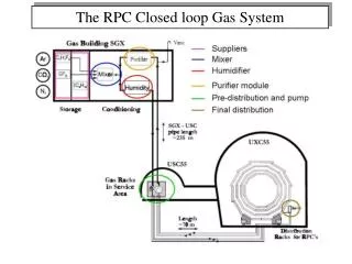
The closed loop system at ISR The closed loop worked at the GIF for many months with a total flow of 40 l/h and a fresh mixture input of 2 l/h (5% of the total flow) • We moved the system at ISR in January. • Preliminary tests has been done in order to verify the possible use in the “ISR conditions”: • Total flow of 150-200 l/h • Connect and disconect frequently the RPC from the gas system CMS week 14 March 2005 Roberto Guida
Total flow of 150-200 l/h • The system was tested succesfully with an argon bootle (short test: only few hours) • During this test 4 RPC were connected • A total flow of 200 l/h was reaced with an input flow of 10 l/h (5% of the total flow)
Connect and disconect frequently the RPC from the gas system • The RPCs under test change every 2-3 weeks • It must be avoided the connection of an RPC full of air to the closed loop system (contamination of all the circuit) • It is impossible to stop the gas flow (the system is sensible to pressure variation)
Project • We have forseen an open loop line for the first connection of an RPC and two three ways valves (for each gas line) for the commutation between the open loop to the closed loop • We have already tested this solution with two channel connected to the closed loop and two valves per channel for the commutation
Output Closed Loop Output Open Loop Distrib. Rack Output Part Closed Loop Rack Distrib. Rack Input Part Input Closed Loop Input Open Loop
Ch 1 Ch 2 Op, Cl, Op, Cl, Op, Cl, Op, Cl, Flux contr. Flux contr. Legend RPC Rotameters bubblers Three ways valve
Status of the system • Test of the three ways valve OK • Test of the connection to the general input and output lines OK • 3 new lines for the closed loop (input and output) OK 1 new line for the open loop (input and output) OK Each line is about 100 mt long • Construction of the commutation pannels (between closed and open loop) OK
Construction of the commutation pannels (between closed and open loop) OK 10 channels Bubblers for the open line Input valves output valves
Integration between the present system and the commutation pannels Wednesday 16th March • Development of a system for switch off the HV in case of a stop of the closed loop • Test of the final system