Understanding LC3 Control State Graphs: Completeness, Conflicts, and Sequence Detectors
570 likes | 682 Views
This review delves into LC3 control state graphs, focusing on the concepts of completeness and conflict issues in finite state machines (FSMs). It explains how to create transition tables and next state equations from state graphs, with examples of sequence detectors and one-hot encoding. Key components like the LC3 fetch cycle, cascading counters, and UART asynchronous inputs are discussed, providing insight into the design and analysis of FSMs. By leveraging this understanding, students can effectively analyze and implement state machines in digital systems.

Understanding LC3 Control State Graphs: Completeness, Conflicts, and Sequence Detectors
E N D
Presentation Transcript
Review for Exam 3 LC3 control State Graphs Completeness and conflict issues Creating transition tables and next state equations from state graphs Sequence detectors One-hot encoding Cascaded counters UART Asynchronous inputs
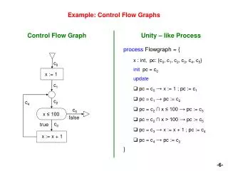
LC3-The Fetch Cycle Fetch0 enaPC ldMAR • MAR PC • MDR Memory[MAR] PC PC+1 • IR MDR selMDR = 1 ldMDR selPC=00 ldPC Fetch1 Fetch2 enaMDR ldIR
Counters and Other Finite State Machines For counters, the state encodings are usually significant 0000 1001 0001 1000 Q0 0010 7 Segment Decoder Q1 Q2 0111 0011 Q3 0110 0100 0101
For general purpose FSMs, the encoding of the states is usually not significant For example, in the following state graph, the Encodings of the state are irrelevant Event 2 … Event 1 Event 1 Event 2 Event 3
State Graphs for Counters with Inputs The INC signal determines whether or not to transition to the next state
Completeness Issues This state graph is not complete. Why not? What happens in state ’10’ when INC’ occurs?
Completeness Issues • In order for a state graph to be complete: • It must completely specify the FSM • Paths leaving a state must specify all POSSIBLE cases • To check for completeness, OR together all of the exiting paths. • If the result is “1” then the design is complete.
Conflict Issues This state graph is not conflict free. Why not? What happens in state ’10’ when CLR and INC occur simultaneously?
Conflict Issues • In order for a state graph to be conflict free: • It must completely specify the FSM • For a given set of input conditions, the transition • from a state must be unique • To check for conflicts, AND together all pairs of the exiting paths. If the result is “0” for all pairs, the design has no conflicting transitions.
Creating transition tables and next state equations from state graphs
The resulting next state and output equations are: N1 = Q0 + Q1 TDONE’ N0 = TOKEN Q1’ Q0’ CLRT = Q0 SPRAY = Q1
This is a sequence detector. It has 1 input – ‘Xin’. It detects the sequence 0..1..1 on the input. When detected, the output signal ‘Z’ is asserted.
As long as ‘Xin’ is a ‘1’ we stay in state S0. 1..1..1..1..
When we detect a ‘0’ we move to state S1. 1..1..1..1..0..
As long as ‘Xin’ is a ‘0’ we stay in state S1. 1..1..1..1..0..0..0..0..
When we detect a ‘1’ we move to state S2. 1..1..1..1..0..0..0..0..1..
If the next value of ‘Xin’ is a ‘1’ we move to state S3. 1..1..1..1..0..0..0..0..1..1 We have found the sequence 0..1..1 so we also assert the output ‘Z’. We are done!
But what if the next value of ‘Xin’ is a ‘0’? 1..1..1..1..0..0..0..0..1..0.. We move back to state S1 to wait for the next ‘1’.
Problems This machine is only useful for detecting the 1st occurrence of the pattern 0..1..1. After that, it simply loops at state S3 forever while asserting the ‘Z’ output.
Here is a modified version It detects an occurrence of the pattern, asserts the output ‘Z’ for one clock cycle and then goes on to look for the next occurrence of the pattern Note: when transitioning from state S3, a ‘0’ sends the machine to state S1 while a ‘1’ sends it to state S0.
A Mealy Version of the Detector The major difference is that the output ‘Z’ is asserted on the transition ‘Xin’ from state S2. It is a Mealy machine because the output is a function of the current state and the input.
A Mealy machine often allows a reduction in the number of states necessary to implement a machine. Here is a machine which does the same function.
One-Hot Encoding One-Hot encoding has the following characteristics: • There is one flip flop for each state • Only one state bit can be high at a time • One state bit must always be high • It uses more flip flops than dense encodings • Tradeoff is that input forming logic and output forming logic are usually much smaller and simpler.
a’ A b’c a C b B b’c’ Take for example the following state graph
D Q D Q D Q B+ B C+ C State Encoding and Structure A+ A With one-hot encoding, each state has its own flip flop. Note: ‘A’ is the name of a state. It is also the name of the wire coming out from the flip flop for state ‘A’. The same holds true for states ‘B’ and ‘C’
One Hot Encodings • IFL and OFL can usually be created via inspection • Each state bit can be done separately from the others • Lots of don’t cares lead to simple solutions By inspection we can see: a’ A b’c a C b B b’c’
One Hot Encodings • IFL and OFL can usually be created via inspection • Each state bit can be done separately from the others • Lots of don’t cares lead to simple solutions By inspection we can see: A+ = a’A + b’cB + C a’ A b’c a C b B b’c’
One Hot Encodings • IFL and OFL can usually be created via inspection • Each state bit can be done separately from the others • Lots of don’t cares lead to simple solutions By inspection we can see: A+ = a’A + b’cB + C B+ = aA + b’c’B a’ A b’c a C b B b’c’
One Hot Encodings • IFL and OFL can usually be created via inspection • Each state bit can be done separately from the others • Lots of don’t cares lead to simple solutions By inspection we can see: A+ = a’A + b’cB + C B+ = aA + b’c’B C+ = bB a’ A b’c a C b B b’c’
clk Digit1 Digit0 Sequence should be: …-12-13-20-21-22-23-30-…but we get: …-12-23-20-21-22-33-30-… ????? DO NOT TIE CLKinputs on modulesto anything but the clock !!!!!! Even if you tinker untilyou get the right countsequence, you mustguarantee that signalRollover0 has no hazards Digit0 transition from 1-2 makes this difficult if not impossible clk1 2 2 CLR CLR Mod4 Counter Mod4 Counter INC=‘1’ ‘1’ Rollover1 Rollover0 clk Digit1 1 2 Digit0 2 3 0 1 2 Clk1(Rollover0)
Another Common Ripple Counter Sequence is: 0000 0001 0010 0011 0100 0101 0110 0111 1000 1001 1010 1011 1100 1101 1110 1111 0000 So what is the problem? Q3 Q2 Q1 Q0 ‘1’ ‘1’ ‘1’ ‘1’ T Q Q’ T Q Q’ T Q Q’ T Q Q’ CLK
Timing Diagram clk Q0 changes in response to clock edge Only after it changes does Q1’s FF get a clock Only after that does Q2’s FF get a clock Net effect is that all the FF’s change at different times Logic depending on Q3 has very little timeto react before next clock edge Q0 Q1 Q2 Q3
Q3 Q2 Q1 Q0 T Q Q’ T Q Q’ T Q Q’ T Q Q’ ‘1’ ‘1’ ‘1’ ‘1’ Digit1 Digit0 clk1 2 2 CLR CLR Mod4 Counter Mod4 Counter INC=‘1’ CLK ‘1’ Rollover1 Rollover0 clk Do Not Use Asynchronous or Ripple Counters
A Mod4 Counter The right way! Count Value D Q Clr Terminal Count IFL D Q Roll Over Inc
A Dataflow MUX – Version 1 module mux21(q, sel, a, b); input sel, a, b; output q; assign q = (~sel & a) | (sel & b); ] endmodule Much simpler, less typing, familiar C-like syntax. Synthesizer turns it into optimized gate-level design.
A Dataflow MUX – Version 2 module mux21(q, sel, a, b); input sel, a, b; output q; assign q = sel?b:a; endmodule Even simpler, uses C-like ?: construct
16 16 16 A Dataflow MUX – Multi-Bit module mux21(q, sel, a, b); input sel; input[15:0] a, b; output[15:0] q; assign q = sel?b:a; endmodule 2:1Mux a 0 q b 1 sel Same assignment statement works for multi-bit wires as for 1-bit wires. Key Ideas: The predicate must evaluate to true or false (1 or 0) The parts getting assigned must be proper widths.
a 16 16 16 16 16 00 q b 01 4:1 Mux c 10 d 11 2 sel A Dataflow MUX – Multi-Bit module mux21(q, sel, a, b, c, d); input sel; input[15:0] a, b; output[15:0] q; assign q = (sel==0)?a: (sel==1)?b: (sel==2)?c:d; endmodule
UART Character Transmission Line idling Start bit Parity bit Stop bit Mark Space Line idling again 7 data bits The letter ‘W’ (1010111) Mark 1 0 1 1 1 0 0 1 Space Parity bit(odd parity) 7 data bits – Least significant bit first
UART Character Reception Start bit says a character is coming Receiver should sample in middle of bits Mark Space Receiver can use a timer (counter) to time when it samples
UART Character Reception If receiver samples too quickly, see what happens… Mark Space
UART Character Reception If receiver samples too slowly, see what happens… Mark Space Receiver resynchronizes every time a new start bit arrives. Only has to be accurate enough to receive 8-9 bits
UART Receiving • Receiver checks to see if stop bit is there when it expects at end of character • If not, reports framing error to host CPU • New start bit can appear immediately after stop bit • Receiver will re-synchronize on start bit
Transmitter Block Diagram 300 HZ Counter 300Hz EnableCounter Transmitter State Machine Send Count=10 Mod 10 Counter Increment Busy Shift Parity Generator Shift Register ParitySelect Load Dout ParityBit Din 7
Transmitter FSM Send’ Reset/Load, Shift Idle Send Load Load, Busy, ResetCounter, ResetBRG Send’ A one-hot state encoding would make for a simple implementation. Be sure to choose stateencodings and use hazard-free logic minimization that ensures Busy signal will have nohazards… Wait Busy Send Count 300Hz’ 300Hz Count=10 Shift Count=10’ Shift, Increment,Busy
Asynchronous Signals • Problem: asynchronous signals do not respect setup and hold times • Signals may change at any time ok ok bad bad ok ok Tsu Th Clock