Download
1 / 30
340 likes | 675 Views
BKM 3313 APPLIED THERMODYNAMIC. CHAPTER 5 INTERNAL COMBUSTION ENGINES. 5.1 INTRODUCTION. One of the most significant inventions of the 20 th century is the internal combustion (IC) engine Definition

E N D
BKM 3313 APPLIED THERMODYNAMIC CHAPTER 5 INTERNAL COMBUSTION ENGINES
5.1 INTRODUCTION • One of the most significant inventions of the 20th century is the internal combustion (IC) engine • Definition • An engine in which the chemical energy of the fuel is released inside the engine and used directly for mechanical work E : Exhaust cam shaft I : Intake Cam shaft S : Spark plug V : Inlet and exhaust valve W : Water Jacket for cooling flow P : Piston R : Connecting Rod C : Crank shaft
bore tdc stroke bdc l θ a l = connecting rod a = crank shaft θ = crank angle • IC engines use reciprocating piston in a cylinder (block) • The piston operates between the “top dead center” (TDC) and the “bottom dead center” (BDC) • Valves are used to control the flow of gas into and out of engine • Stroke is the largest distance the piston travels • Bore is the diameter of the piston • Other components are piston, block, crankshaft, connecting rod etc.
5.2 TYPES & CLASSIFICATIONS OF IC ENGINES • IC engine can be classified according to: • applications • Automobile, truck, locomotive, light aircraft, marine, portable, power system etc • basic engine design • Reciprocating engine, rotary engine • no of cylinders • 1, 2, 3, 4, 5, 6, 8, 10, 12 etc. • arrangement of cylinder • In-line, V-type, opposed, radial • working cycle • 4-stroke, 2-stroke • fuel • Gasoline, diesel, nitro methane, alcohol, natural gas, hydrogen etc
Inline, 4-cylinder (Straight 4) V-type, 6 cylinder (V6) ENGINE DESIGN & CYLINDER ARRANGEMENT
Opposed, 4-cylinder (Flat 4) Rotary egine ENGINE DESIGN & CYLINDER ARRANGEMENT
4-STROKE ENGINE • 4-Stroke • Requires 4 stroke of piston to complete a cycle • 1-2 Induction stroke • Inlet valve open. Exhaust valve is closed. BDC to TDC. Air + fuel is induced. • 2-3 Compression stroke • Air + fuel is compressed to TDC. Spark occurred at S and combustion occurs mainly at constant volume. Large increase in pressure and temperature. • 3-4 Working stroke • Hot gas expand pushing the piston down to BDC. Exhaust valve open at E to assist exhaustion. Inlet valve is still closed. • 4-1 Exhaust stroke • The gas is force to exit the cylinder. Piston moved to TDC. Inlet valve is still closed. • 2 revolution of crank shaft per cycle
START INTAKE COMPRESSION SPARK EXHAUST POWER
2-STROKE ENGINE • 2-Stroke • Requires 2 stroke of piston to complete a cycle • First stroke : BDC – TDC (Both compression and induction stroke) • As piston ascends on the compression stroke, the next charge is drawn into crankcase C as the spring loaded valve, S open automatically. Ignition occur before TDC. Both transfer and exhaust port is uncovered. • Second stroke: TDC – BDC ( Both working and exhaust stroke) • At TDC working stroke begin. As the piston descend through about 80%, the exhaust port is uncovered and exhaust begin. The transfer port is uncovered later due to the shape of the piston and the position of the port. The descending piston push the air to enter the cylinder through the transfer port. • 1 revolution of crank shaft per cycle • Less efficient compared to 4 stroke • High power-to-weight ratio • Suitable for small applications
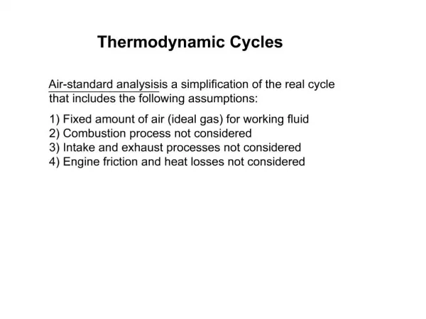
5.3 THE AIR STANDARD CYCLES • Before we could discuss in depth about IC engines, let us look at several types air standard cycles. • We will discuss three standard cycles : • Otto cycle • Diesel cycle • Dual combustion cycle • The air standards cycles are ideal cycles used as a yardstick for the actual cycles. • There are few assumptions applied to the cycles: • Working fluid is air behaving as ideal gas • All process in the cycle are internally reversible • Combustion process is replaced by a heat addition process from an external source • Exhaust process is replaced by a heat rejection process • No chemical reaction
VC b tdc VD L bdc l θ a 5.4 PERFORMANCE CRITERIA OF IC ENGINES GEOMETRICAL PARAMETERS • Referring to the diagram • Note: • “Indicated” refers to the values obtained by analysis on the cycle (i.e. Indicated Power, Indicated MEP) • “Brake” refers to the values obtained through experimental methods (i.e. Brake Power, BMEP) • VD is multiplied by no of cylinder for multi-cylinder engines
INDICATED POWER • Definition: The rate of indicated cycle work. • How it’s being measured: Using indicator diagram obtained from the engine. • Net work done per cycle = area of power loop – area of pumping loop • Therefore indicated mean effective pressure, Pi Note: the constant will depends on the scales of the recorder. Normally the units of the constant are either bar/mm or kPa/mm
INDICATED POWER • For one cylinder engine, where L = stroke A = area of piston • For N rpm and n cylinder,indicated power can be written as:
EXAMPLE 5.4 Based of the data given, determine the engine indicated power: Net are of diagram = 210 mm2 Length of diagram = 28 mm Constant = 0.8 bar/mm Engine type = 4 stroke No of cylinder = 4 Piston area = 100 cm2 Stoke = 12 cm Engine speed = 3000 rpm
BRAKE POWER • It is the measured output of the engine (actual power). • The engine is connected to a brake dynamometer which can be loaded in such a way that the torque exerted by the engine can be measured. • The torque is obtained by reading off a net load, W at a known radius, r from the axis rotation and hence the torque is given by • The brake power is given by • Nowadays torque can be measured directly and bp is obtained directly using above equation.
ENGINE DYNAMOMETER
FRICTION POWER & MECHANICAL EFFICIENCY • The difference between the ip and bp is the friction power, fp. • It is defined as the power required to overcome the frictional resistance of the engine parts. • The mechanical efficiency is defined as • The value lies between 80 to 90%.
BRAKE MEAN EFFECTIVE PRESSURE • The brake power of an engine can be obtained accurately using dynamometer. • From equation and we will get • Since mand ip are difficult to obtain, they may be combined and replace by a brake mean effective pressure pb.
BRAKE THERMAL EFFICIENCY • Generally we define efficiency as • For IC engine, the actual output is brake power and the input is the chemical energy of the fuel supplied • The value of NKR is a standard value. For diesel, NKR = 45.5 MJ and for petrol, NKR = 44.2 MJ
INDICATED THERMAL EFFICIENCY • Indicated thermal efficiency is defined as • If we divide bt with it
SPECIFIC FUEL CONSUMPTION • It is defined as mass flow rate of fuel per unit power output. • It is a criterion of economical power production
EXAMPLE 5.5 Based of the data given, determine the brake power, brake mean effective pressure, brake thermal efficiency and sfc. Type of engine = 4 cylinder, 4 stroke petrol engine Bore = 55 mm Stroke = 100 mm Engine speed = 3500 rpm Torque arm, r = 0.45 m Net brake load = 160 N Mass rate (fuel) = 0.0014 kg/s NKR = 44.2 MJ
5.5 OTHER TYPE OF ENGINE TESTING-MORSE TEST • Since it is very difficult to obtain indicated power, Morse Test is introduce to give alternative solution. • The test is suitable for multi cylinder engine. • Testing procedures: • Engine is set to run at certain speed, N and torque is measured • One cylinder is cut out by shorting the plug. • When the speed falls, load is reduced to restore the engine speed. • The torque is measured again. • The plug is placed back and another cylinder is cut out by shorting its plug. • Speed is again restored and torque is again measured. • The procedures is repeated until all cylinder is simultaneously cut out.
MORSE TEST • If it is a 4 cylinder engine: • When cylinders are cut off
MORSE TEST • Subtracting the equations, for cylinder 1 • So for each cylinder, • Then for the engine
EXAMPLE 5.5 A Morse test is carried out to a 4 cylinder, 4 stroke petrol engine. Based on the data given, determine the mechanical efficiency of the engine: W = 120N W1-off = 86.8N W2-off = 81.4N W3-off = 88.6N W4-off = 82.1N