Download
1 / 47
470 likes | 486 Views
Explore the significance of nanomechanics in computational nanotechnology, enabling control at the molecular level for creating nanomachines and novel functional devices. Learn about carbon nanotubes, molecular dynamics, and stress analysis at the atomic scale.

E N D
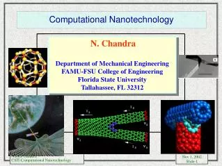
Role of Nanomechanics in Computational Nanotechnology N Chandra, S Namilae and C Shet Collaborators: Leon van Dommelen (ME/FSU) Ashok Srinivasan (CS/FSU)
Computational Modeling in Nanotechnology • By nature, humans live, work and play in the macroscale. But they have the unique ability to “think” in the nanoscale. • Control must inherently come from the MACROSCALE because that is the scale where humans reside. • MANY PATHS TO FOLLOW • Biochemistry: Custom protein design • Chemistry: Molecular recognition • Physics: Scanning probe microscopy Computing: Molecular modeling • Engineering: Molecular electronics • Engineering: Quantum electronic devices • Engineering: Nanocomposites • Engineering: Nanomaterials engineering “...thorough control of the structure of matter at the molecular level. It entails the ability to build molecular systems with atom-by-atom precision, yielding a variety of nanomachines. These capabilities are sometimes referred to as molecular manufacturing.” - K. Eric Drexler, 1989 To manipulate things which we cannot see without the unaided eye but indeed understand, we must employ predictive methods: Computational Tools. If you can’t model it, you can’t build it!
The Scale of Things -- Nanometers and More 1 cm 10 mm 10-2 m Head of a pin 1-2 mm 21st Century Challenge 1,000,000 nanometers = 10-3 m Ant ~ 5 mm 1 millimeter (mm) Microwave Dust mite 200 mm 0.1 mm 100 mm 10-4 m Fly ash ~ 10-20 mm Human hair ~ 10-50 mm wide The Microworld 0.01 mm 10 mm 10-5 m Infrared Red blood cells with white cell ~ 2-5 mm 1,000 nanometers = 10-6 m 1 micrometer (mm) Visible 0.1 mm 100 nm 10-7 m Combine nanoscale building blocks to make novel functional devices, e.g., a photosynthetic reaction center with integral semiconductor storage Ultraviolet 0.01 mm 10 nm The Nanoworld 10-8 m Nanotube transistor Nanotube electrode ~10 nm diameter ATP synthase 10-9 m 1 nanometer (nm) Soft x-ray DNA ~2-1/2 nm diameter 10-10 m 0.1 nm Carbon nanotube ~2 nm diameter Quantum corral of 48 iron atoms on copper surface positioned one at a time with an STM tip Corral diameter 14 nm Things Natural Things Manmade MicroElectroMechanical devices 10 -100 mm wide Red blood cells Pollen grain Zone plate x-ray “lens”Outermost ring spacing ~35 nm Atoms of silicon spacing ~tenths of nm Office of Basic Energy Sciences Office of Science, U.S. DOE Version 03-05-02
Forces, Displacements, Velocities, energy Discrete lattice Dynamics Ensemble Averages Thermodynamics Stress,strain, energy Homogenous Continuous Description Should we define continuum quantities at atomic scale ? • Enables application of well developed continuum theories • Inelasticity, Failure, Damage and criterion thereof • Larger systems possible e.g. CNT composites Problems? Existence and Uniqueness Nanomechanics Issues
Compute Continuum quantities -Kinetics (,P,P’ ) -Kinematics (,F) -Energetics Use Continuum Knowledge - Failure criterion, damage etc Molecular Dynamics -Fundamental quantities (F,u,v) Mechanics at atomic scale Stress-strain required for local behavior
Carbon Nanotubes • Carbon Nanotubes Graphite sheet rolled into a tube • Length ~ 100 nm to few m Diameter~ 1 nm • Chirality based on rolling direction • Found as single wall and Multi wall tubes
Carbon Nanotubes (CNTs) • CNTs can span 23,000 miles without failing due to its own weight. • CNTs are 100 times stronger than steel. • Many times stiffer than any known material • Conducts heat better than diamond • Can be a conductor or insulator without any doping. • Lighter than feather.
Sp3 Hybridization here Defects in carbon nanotubes (CNT) • Mechanical properties • stiffness Reduction. • Plastic deformation and fracture • Enhanced Chemical activity • Electrical properties • Formation of Y-junctions • End caps • Other applications • Hydrogen storage, sensors etc • Defect types • Point defects e.g Vacancy • Topological defects e.g. 5-7-7-5 defect • Hybridization defects 1Ref: D Srivastava et. al. (2001)
Stress at atomic scale • Definition of stress at a point in continuum mechanics assumes that homogeneous state of stress exists in infinitesimal volume surrounding the point • In atomic simulation we need to identify a volume inside which all atoms have same stress • In this context different stresses- e.g. virial stress, atomic stress, Lutsko stress,Yip stress
Virial Stress Stress defined for whole system For Brenner potential: Includes bonded and non-bonded interactions (foces due to stretching,bond angle, torsion effects)
BDT (Atomic) Stresses Based on the assumption that the definition of bulk stress would be valid for a small volume around atom - Used for inhomogeneous systems
Lutsko Stress - fraction of the length of - bond lying inside the averaging volume • Based on concept of local stress in • statistical mechanics • used for inhomogeneous systems • Linear momentum conserved
Averaging volume for nanotubes • No restriction on shape of averaging volume (typically spherical for bulk materials) • Size should be more than two cutoff radii • Averaging volume taken as shown
Strain calculation in nanotubes • Defect free nanotube mesh of hexagons • Each of these hexagons can be treated as containing four triangles • Strain calculated using displacements and derivatives shape functions in a local coordinate system formed by tangential (X) and radial (y) direction of centroid and tube axis • Area weighted averages of surrounding hexagons considered for strain at each atom • Similar procedure for pentagons and heptagons Updated Lagrangian scheme is used in MD simulations
Elastic modulus of defect free CNT -Defect free (9,0) nanotube with periodic boundary conditions -Strains applied using conjugate gradients energy minimization • All stress and strain • measures yield a Young’s • modulus value of 1.002TPa • Values in literature range • from 0.5 to 5.5 Tpa. Mostly • around 1Tpa
Local elastic moduli of CNT with defects • Type I defect E= 0.62 TPa • Type II defect E=0.63 Tpa • Reduction in stiffness in the presence of defect from 1 Tpa • -Initial residual stress indicates additional forces at zero strain • -Analogous to formation energy
Stress and Strain profiles Note the stress and strain amplification
Bond angle and bond length effects • Pentagons experiences maximum bond angle change inducing considerable longitudinal strains in facets ABH and AJI • Though considerable shear strains are observed in facets ABC and ABH, this is not reflected when strains are averaged for each of hexagons
Evolution of stress and strain Strain and stress evolution at 1,3,5 and 7 % applied strains Stress based on BDT stress
Effect of Diameter and Chirality More pronounced effect with variation in chirality
Residual stress at zero strain • Stress is present at zero strain values. • This corresponds to stress due to curvature • It is found to decrease with increasing diameter • Basis for stress calculation graphene sheet
Issues in Nanotube composites • Controlling alignment during processing • Homogeneous distribution (spatial) • Orientation control (directional) • Processing induced residual stresses • Interface bonding (at atomic level) • Load transfer • Fracture/load shedding Strong Interfaces By Chemical Bonding ? Interface Bounding surface with physical / chemical / mechanical discontinuity
Chemical bonding at CNT- matrix interfaces • Wagner et.al. (1998) indirect measurement of interface strength ~500MPa • Qian et.al. (2002) significant load transfer across interface in CNT-polystyrene composites • Eitan et. al (2003) report carboxylization of CNT and predict covalent bonding with epoxy matrix • Gong and coworkers (2000) improved composite properties by coating nanotubes with surfactants • Frankland et. al.(2002) based on MD simulation suggest increased interface strength with chemical bonding
Functionalized nanotubes • Objective • Study Deformation of functionalized nanotubes • Study deformation on nanotubes in composites • Change in hybridization (SP2 to SP3) • Experimental reports of different chemical attachments • Application in composites, medicine, sensors
Simulation Parameters • Various nanotubes with hydrocarbon attachments, vinyl and butyl in central portion • Temperature 77K and 3000K • Applied displacement at both ends at 0.05A/1000 steps • Lutsko stress computed on volume shown
Functionalized nanotubes contd • Increase in stiffness observed by functionalizing • 20 attachments show about 10% increase in local elastic modulus
Local Stiffness of functionalized CNTs • Stiffness increase is more for higher number of chemical attachments • Stiffness increase higher for longer chemical attachments
Contour plots Stress contours with one chemical attachment. Stress fluctuations are present
Sp3 Hybridization here Radius variation • Increased radius of curvature at the attachment because of change in hybridization • Radius of curvature lowered in adjoining area
4.7 % strain 7 % Strain 7.8 % Strain 9 % Strain 5.737 % strain 6.14 % strain 11 % Strain 10 % Strain 7 % Strain Defect evolution and onset of plastic deformation • Defect evolution starts at about 7% strain • (10,10) CNT T=3000K
Evolution of defects in functionalized CNT • Defects Evolve at much lower strain of 4.5 % in CNT with chemical attachments Onset of plastic deformation at lower strain. Reduced fracture strain
Multi scale model (I Molecular dynamics) (10,10) CNT with varying no of hydrocarbon attachments Applied displacements at 300K
Interfacial shear Interfacial shear measured as reaction force of fixed atoms Max load Typical interface shear force pattern. Note zero force after Failure (separation of chemical attachment) After Failure 250,000 steps
Debonding Rebonding Failure Debonding and Rebonding of Interfaces
Variation in interface behavior Homogenization ?
Multi scale approach (II : FEM/cohesive zone model) • Assumptions • Nanotubes deform in linear elastic manner • Interface character completely determined by traction-displacement plot CZM enables modeling of surfaces before and after fracture
Preliminary result: Numerical pull-out test • Pull out of nanotube from polymer matrix modeled with CZM/ atomically informed interface characteristics Scaled up version of the previous test nanotube length 2 microns
Shear Lag Studies Contours of Normall Stress s22at d = 0.72 nm Contours of Shear s12 Stress at d = 0.72 nm Contours of Normal Stress s22 at d = 12 nm Contours of Shear s12 Stress at d = 12 nm separation
Shear Lag model Applications of the multiscale model Composite effective properties
Summary • Local kinetic and kinematic measures are evaluated for nanotubes at atomic scale • There is a considerable decrease in stiffness at 5-7-7-5 defect location in different nanotubes • Defect-defect interactions • Functionalization of nanotubes results in increase in stiffness • Onset of inelastic deformation characterized by evolution of topological defects occurs at lower strains in functionalized tubes • Interface constitutive behavior has been modeled using MD and this information is passed to continuum model using CZM
Interaction between defects • Stiffness reduction in defects placed at different distances along length • Defects placed close to each other experience more loss of stiffness • If distance between the defects is greater than 42 A i.e. 30*l , it does not effect stiffness Variation of stiffness loss with spacing of two interacting defects, placed along the length of the tube.
Non-interacting Defects • Reduction in stiffness increases linearly with number of defects when distance between them > 30*l • Linear damage model predicts this Variation in stiffness loss for with the number of non-interacting defects placed along the length of the carbon nanotube.
Prediction of Reduction in stiffness A simple damage like model predicts reduction in stiffness when number of defects are present