Download
1 / 38
410 likes | 543 Views
Explore the selection of materials and shapes for strong and enduring non-biological muscles in steam turbines for power plants. Learn about the anatomy and working principles of steam turbines to efficiently convert chemical energy into mechanical or electrical energy. Discover the importance of high pressure, micro kinetic energy, and the two-step conversion process in enhancing turbine performance. This comprehensive guide covers the classification of rotors, blade interactions, and mechanical arrangements to optimize the efficiency of steam turbines in power generation.

E N D
Turbines for Steam Power Plants P M V Subbarao Professor Mechanical Engineering Department I I T Delhi Selection of Materials and Shape for Strong & Enduring Non-Biological Muscles ……
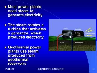
Development of A Sustainable Non-Biological Beast • The steam Power Plant is the largest non-biological beast . • Needs an elaborate anatomy for efficient conversion of chemical energy into Mechanical/Electrical energy. • The working fluid is the blood of this animal. • The pump is the heart of this beast & cyclically induces life into the working fluid. • The steam generator is the digestion system of this beast. • The steam turbine is the Muscle system of this beast. • The supercritical steam turbines are the strongest and most efficient non-biological muscles. • An essential requirement for human development.
Power Plant Steam Turbines A Two Step Conversion of Microscopic Kinetic Power to Shaft Power…….
High Pressure High MKE Steam System Shaft power to generator Dead Steam Dead must be properly recycled
Thermodynamic Validation of Flowing Steam Work Drop in KE Increase in MLE Vi Steam with High KE Negligible MKE Ub Ve Low KE Low MLE Work is said to be done by a system iff the sole effect external to the system can be reduced to raising of weight
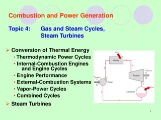
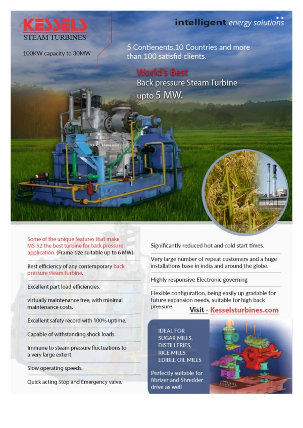
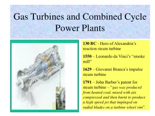
The Steam Turbine • The more modern device to extract shaft power from Microscopic kinetic Power is the steam turbine. • Steam turbines have been the norm in various land based power plants for more than 100 years. • Turbine is a flow device develops a variable pressure form inlet to outlet. • A flowing steam performs work transfer, while moving from high inlet pressure (Live Steam) to low outlet pressure (Dead Steam). • The volume of steam continuously increases during this process. • The infinitesimal work done by a flowing fluid is defined as • Sign is important part of this definition. • Steam flowing in the direction of decreasing pressure performs +ve work.
Continuous Generation of Power • How to introduce finite mass flow rate of steam? • Area for Flow of Fluid. • Proportional to the Length of the Blade. • More Number of Blade Spacings.
Concept of Two Step Conversion : Kinetic Power to Shaft Ppwer • Steam turbine is a two part device: • Part 1:Energy Converter : Nozzles or Stationary Blades • Part 2: Energy Exchanger: Rotor or Moving Blades.
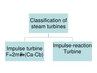
Classification of Rotors or Rotor Blades • Single Job Rotors: Only Exchange of Macro Kinetic Power from steam to Shaft Power via blades. • Also called as Impulse Blades/rotor. • Dual Job Rotors: Both energy conversion and Energy Exchange. • Known as Reaction Blades/rotor. • Best choice for Large Power Plant Turbines
U Vr1 Va1 Va1 Inlet Velocity Triangle U Va2 Vr2 Exit Velocity Triangle Top View of the Steam & Blade Interactions Vr1 U Vr2
The Velocity Triangles U b1 a2 a1 b2 Va1 Va2 Vr1 Vr2 Va1: Inlet Absolute Velocity Vr1: Inlet Relative Velocity Vr2: Exit Relative Velocity Va2:Exit Absolute Velocity a1: Inlet flow Angle. b1: Inlet Blade Angle. b2: Exit Blade Angle. a2: Exit flow Angle.
Selection of The Velocity Triangles Ub a1 b1 U U U b1 b1 b1 a2 a2 a2 a1 a1 a1 b2 b2 b2 Va1 Vr1 a2 b2 Va1 Va1 Va1 Va2 Va2 Va2 Vr1 Vr1 Vr1 Va2 Vr2 Vr2 Vr2 Vr2 Va1: Inlet Absolute Velocity Vr1: Inlet Relative Velocity Vr2: Exit Relative Velocity Va2:Exit Absolute Velocity a1: Inlet flow Angle. b1: Inlet Blade Angle. b2: Exit Blade Angle. a2: Exit flow Angle.
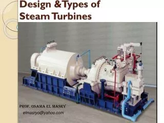
Mechanical Arrangements of Steam Turbines • The blade velocity is defined at mean diameter of rotor wheel. • For same wheel speed, the blade velocity is directly proportional to blade height. • The height of the blade is proportional to specific volume of steam. • Solutions to Turbo-machinery Speed Issues (TSI). • Tandem Reheat Steam Turbine • Cross Compound Steam Turbine
Large-Capacity Steam Turbines for Fossil Thermal Power Plant
Steam Volume Variation HP Range Specific volume, m3/kg Steam Path, Mpa
Steam Volume Variation IP Range Specific volume, m3/kg Steam Path, Mpa
Steam Volume Variation LP Range Specific volume, m3/kg Steam Path, Mpa