Download
1 / 32
480 likes | 1.97k Views
Chapter 5 Steam Engine, Steam and Gas Turbines. Steam Power System. Steam power system is a system in which the heat energy of the steam is used to produce mechanical power.

E N D
Chapter 5Steam Engine, Steam and Gas Turbines
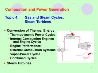
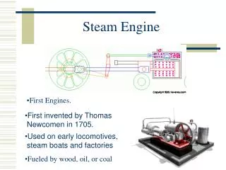
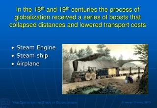
Steam Power System • Steam power system is a system in which the heat energy of the steam is used to produce mechanical power. • Various types of fuels (coal, diesel, natural gas, geothermal, nuclear, etc.) are used to produce the high quality of steam, i.e., superheated steam and then the thermodynamic expansion process is used to convert the heat energy of the steam into mechanical power. • The steam engine was developed by James Watt in 1763 after that steam turbines, gas turbines, and I.C. engines came into picture.
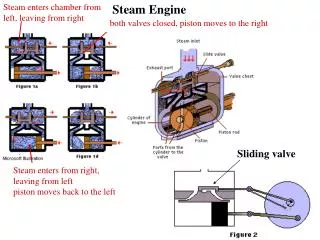
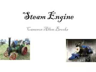
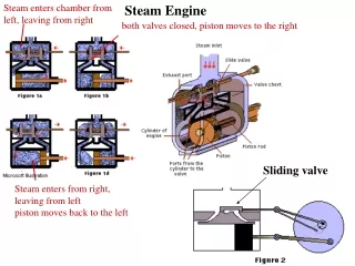
Steam Engines • A steam engine is a reciprocating heat engine that performs mechanical work by using steam as its working fluid. • Steam engines are external combustion engines based on modifiedRankine cycle, where the working fluid is separate from the combustion products.
Actual Indicator Diagram • Mean effective pressure • Mean effective pressure with clearance volume
Work done per cycle • Work done per cycle with clearance volume
Rankine Cycle • Four processes in the Rankine cycle • Process 1–2 (Pumping Process) • Process 2–3 (Heating Process) • Process 3–4 (Expansion Process) • Process 4–1 (Condensation Process)
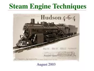
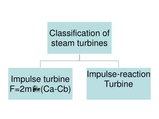
Steam Turbine • Steam turbine is a prime mover, which converts heat energy of steam into mechanical energy by rotating motion of the blade. • Total energy conversion involves two types of steam expansion—expansion of steam in nozzle and expansion of steam in turbine blades. • Classification of Steam Turbine 1. Impulse turbine. 2. Impulse-reaction turbine.
Difference Between Impulse and Reaction Turbine Impulse Turbine 1. Pressure drops occur only in nozzles. 2. It has constant blade channel area. 3. It has profile type blades. 4. It can be used for small power development. 5. It has lower efficiency due to high losses. Reaction Turbine 1. Pressure drops occur in moving blades as well as fixed blades. 2. It has varying blade channel area. 3. It has aerofoil blade cross-section. 4. A considerable power developed is possible. 5. It has higher efficiency than that of impulse turbines.
Impulse Turbine (de-Laval Turbine) where Fdt is impulse and d (mv) is change in momentum.
Blade Friction Factor: • Energy loss due to friction in blade • Tangential Thrust • Axial Thrust • Blade Work or Diagram Work
Blade or diagram efficiency • Maximum blade efficiency and optimum velocity ratio
Compounding of Impulse Turbine If steam at very high pressure is allowed to expand in single stage of turbine, the blade velocity will be too high. Such a high rotational speed cannot be used properly and also there will be velocity loss at the exit of the blade due to high exit velocity of steam. Therefore, to overcome these difficulties, the turbine is compounded or staged. In compounded turbines, steam is made to expand in number of stages instead of single stage . 1. Pressure compounding or Reteau staging. 2. Velocity compounding or Curtis staging. 3. Pressure–velocity compounding.
Pressure Compounding or Reteau Staging Pressure compounding is splitting of whole pressure drop of steam from steam chest pressure to condenser pressure into series of small pressure drops across several stages of impulse turbine.
Velocity Compounding or Curtis Stages • In this compounding, whole pressure drop takes place in nozzle (only one row) and remains constant in fixed and moving blades. Velocity of steam remains constant in fixed blades and decreases in moving blades.
Pressure–Velocity Compounding It is combination of pressure compounding and velocity compounding. There are two rotors and only two rows of moving blades are attached on each rotor because two row wheels are more efficient than three row wheels. The steam on passing through each row of moving blades reduces its velocity but pressure remains constant during passing through these blades.
Impulses-reaction Turbine (Reaction Turbine) • If steam expands both in nozzle as well as in blades of turbine, i.e., pressure at inlet of the turbine is more than that of outlet, it is known as impulse-reaction turbine. • In this case, expansion of steam in nozzle creates impulse on blades and reaction due to minor expansion of steam during passing through moving blades. • The small drop in pressure of steam in the moving blades gives back pressure to the moving blades in the direction opposite to the velocity. • In this turbine, there are stages of fixed blades and moving blades; fixed blades act as nozzles that create an impact on the moving blades by reducing the pressure and increasing the velocity.
Degree of Reaction (R) • Reheat Factor
Velocity Diagram for Reaction Turbine • Diagram efficiency of blades
Governing of Steam Turbines • Throttle governing. • Nozzle control governing. • By-pass governing.
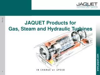
Gas Turbines • Gas turbine is a rotating type prime mover which converts heat energy of gas/air (at high pressure and temperature) into mechanical work. • The principle of operation is based on Newton’s Second Law of Motion. The motive power is obtained by the change in momentum of high-velocity jet impinge on curved blades of the turbine. • A simple gas turbine consists of • Compressor • Combustion chamber • Turbine
Classification of Gas Turbine • On the basis of thermodynamic cycle, there are two types of gas turbines: 1. Constant pressure cycle, i.e., Joule or Brayton cycle—Heat addition and rejection are done at constant pressure. 2. Atkinson cycle—Heat addition at constant volume and rejection at constant pressure. • On the basis of path of the working fluid, gas turbine can be classified as • Open cycle gas turbine—Working fluid enters from atmosphere and exhausts to atmosphere. It works similar to I.C. engine. • Closed cycle gas turbine—Working fluid is confined within the plant and recirculated. The working is very similar to external combustion engines.
Joule or Brayton Cycle • Process 1–2: Isentropic compression in the compressor thus raising pressure and temperature from P1, T1 to P2, T2. • Process 2–3: Addition of heat at constant pressure raising temperature from T2 to T3. • Process 3–4: Isentropic expansion of air from high pressure and temperature to low pressure and temperature and thus doing work. • Process 4–1: Rejection of heat at constant pressure to restore the original state of air.