Download
1 / 22
220 likes | 238 Views
This update provides an overview of the progress made on the RF cavities, frequency tuners, and other components for the MICE project at Lawrence Berkeley National Laboratory. The physical measurements, frequency measurements, and future work are discussed.

E N D
Steve Virostek Allan DeMello Lawrence Berkeley National Laboratory MICE RFCC ModuleUpdate MICE CM27 at RAL, UK July 8, 2010
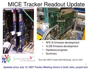
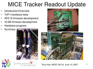
MICE RFCC Module Update Overview • RF cavities • RF cavity frequency tuners • Cavity RF couplers • Beryllium windows • RFCC module schedule
RF Cavity Progress Summary • Completion of second set of five cavities by Applied Fusion expected in September 2010 • Physical (CMM) measurement of first five cavities recently completed • RF frequency and Q measurements of first five cavities recently completed • Local (near LBNL) electro-polishing company has been identified and discussions initiated
RF Cavity Fabricator - Applied Fusion, Inc. • E-beam welding of stiffener rings and equators complete • Port holes are machined and ready for port pulling
RF Cavity Physical Measurement • Physical measurement of the first five cavities using a CMM is complete • Specialized tooling was procured to allow measurement of cavity inner profile • Cavities are ~10 mm narrower than nominal (likely caused by cooling tube brazing), but no issues are expected • Second set of five cavities will be inspected when delivered to LBNL
RF Cavity Frequency Measurement • RF frequency measurements for the first five cavities are complete • The three Be windows at LBNL have also been characterized • Refer to Derun Li’s talk for details
RF Cavity Electropolish Vendor • The inside surface of each RF cavity will be electropolished • Discussions under way with local company Milpitas California (40 mi to LBNL) Electro-polish tank dimensions: 12' Long x 5' Wide x 6' Deep Large SS piping weldment at AET
RF Cavity Future Work • Physical (CMM) and frequency measurements will be performed on the remaining five cavities when they become available • Leak and flow check of the cooling tubes will be performed • The inside surface of each RF cavity will be mechanically buffed and electropolished • The ten cavities will be “tuned” to each other through plastic deformation (if necessary) for best center frequency (to be done at LBNL)
RF Cavity Frequency Tuner Progress • Tuner design is complete • One full size tuning arm (for testing the system) has been fabricated • Aluminum test cylinder (1/6 of cavity) has been fabricated to replicate the cavity stiffness • Assembly of a pneumatic actuator has been completed • Control system components have been assembled into a working system • Integrated tuner system has been tested, and ±2 mm of tuner arm motion has been confirmed
RF Cavity Frequency Tuner Overview • 24 dynamic cavity frequency tuners per module • Tuner Actuator • Tuner Flexure Arm • Tuners operate in a bi-directional “push - pull” mode (±2 mm) • Tuning will be automatically achieved through a frequency feedback loop
RF Cavity Frequency Tuner Components • Tuner/actuators are thermally independent of the vacuum vessel • Dual–action actuator • Actuator is • screwed into • the tuner arm • Flexure • tuner arm • Fixed • connection to cavity
Prototype Actuator Design • Dual–action (push/pull) actuator • Actuator mechanical components (except bellows) were fabricated and assembled at LBNL • Forces are transmitted to the cavity stiffener ring by means of “push-pull” loads applied to the tuner flexure arms by the dual action actuator assembly
Tuner System Analysis Review • The Von Mises stress at the flexure is 205 Mpa (30 ksi) • The input load by the air actuator is 3.56 kN (800 lb) • The tuner arm displacement is 5.4 mm (10.9 mm bi-directional) • The cavity displacement is 1.0 mm per side
Tuner Flexure and Test Ring • Full size (3” thick stainless steel) prototype tuner flexure with actuator and test ring • Prototype actuator threaded into tuner arm • Aluminum test ring with spring rate equivalent to 1/6th of a cavity
Prototype Tuner Arm Test Setup Test set-up includes: 1. Actuator, tuner arm and test ring 2. Control regulators and manifolds 3. Computer control
RF Cavity Tuner Control System • Emerson ER3000 electronic pressure controllers – one for each side of the actuator • ±0.1% accuracy (over 110 psi range) • Remote computer controlled for frequency feedback • 16 total modules required for two RFCC modules
RF Cavity and Frequency Tuner • Prototype tuner/actuator mounted on cavity
RF Cavity Frequency Tuner Future Work • Order parts for 5 more (6 total) actuators (incorporating any refinements from the prototype) • Fabricate 5 more tuner flexures • Build a cavity suspension frame • Test the RF tuning system with 6 tuners and actuators on a cavity • Actuators will be manifolded together • Frequency measurements will be taken to verify the frequency tuning range
Toshiba RF Window for Cavity RF Coupler • Assembly drawing of cavity RF coupler showing Toshiba RF Window
Toshiba RF Window • Quote for 10 Toshiba RF windows has been obtained • U. Miss. Is in the process of placing the order (~$180k) • Slight modification to SNS design (now all metric threads)
Beryllium Window Update • 3 of 11 windows have been received by LBNL from Brush-Wellman • Windows have been characterized during cavity frequency measurements • An additional 8 windows are expected to be delivered in the next two months