Download
1 / 40
440 likes | 534 Views
This project involves the finite element simulation of a vertical drop test of a Boeing 737 fuselage section with overhead bins. Detailed analysis, results, and conclusions are presented based on the simulation and experimental data collected during the drop test.

E N D
Finite Element Simulation of a Vertical Drop Testof aBoeing 737 Fuselage Section A. Byar,J. Awerbuch, A. Lau and T. Tan Drexel University Department of Mechanical Engineering and Mechanics Philadelphia, Pennsylvania Presented at Third Triennial International Fire & Cabin Safety Research Conference, October 22-25, 2001, Atlantic City, NJ
Acknowledgement This work is sponsored by the FAA William J. Hughes Technical Center under Grant No.99-P-0056, and is part of the FAA-Drexel Fellowship Research Program. Gary Frings and Tong Vu are the program monitors.
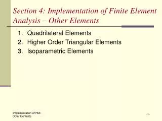
Outline of the Presentation • Objectives • Drop Test of B737 Fuselage Section • Finite Element Model and Simulation • Results • Deformation Time Histories of Frames • Acceleration Time Histories of Frames, Seat Tracks, and Overhead Bins. • Load Time Histories of the Supporting Structures of the Overhead Stowage Bins • Conclusions and Summary
Objectives • Develop a finite element model and conduct a dynamic simulation of the drop test of a Boeing 737 fuselage section. • Refine the finite element model through a comparison of the simulation and experimental results. • Develop a finite element based methodology to provide guidance for future testing conditions or configurations, and to simulate drop tests of other airframes that may be of interest in the future.
Drop Test of the B737 Fuselage Section With Two Overhead Bins Performed in November 2000 at the FAA William J. Hughes Technical Center • Ten foot long B737 fuselage section • Seven frames, from FS 380 to FS 500 • A cargo door on the right-hand side • Two different overhead stowage bins • 18 seats with dummy passengers • Luggage stowed in the overhead bins and the luggage compartment • Fully instrumented with strain gages and accelerometers • 30 ft/sec initial impact velocity
Front View Back View Hitco Bin Heath Tecna Bin Drop Test of the B737 Fuselage Section
Camera Mounts Hitco Bin Heath Tecna Bin Forward Right Left Extra Under- Floor Beams Under-Floor Beams Finite Element Model Cargo Door
Seat Tracks Finite Element Model Camera Mount Heath Tecna Bin Forward Right Left Floor Aft Cargo Door
Camera Mounts Hitco Bin Heath Tecna Bin FS 380 FS 400 FS 420 FS 440 FS 460 Frame Reinforcement FS 480 FS 500 FS 380 FS 400 FS 420 FS 440 FS 460 FS 480 FS 500 Reinforcement Short Beams Cargo Doorframe Finite Element Model Forward
Cylindrical Rod Vertical Tie Rod Vertical Link Horizontal Link Short Beam Finite Element Model Hitco Bin FS 480 FS 460 FS 420 FS 400 • Bin is modeled with shell elements • All supporting members are modeled with beam elements
C Channel Strut Longitudinal Channel L Bracket Finite Element Model Heath Tecna Bin FS 480 FS 460 FS 420 FS 400 • Bin and C Channels are modeled with shell elements • All other supporting members are modeled with beam elements
Finite Element Model 57,589 Nodes, 56,652 Shell Elements, 67 Beam Elements. Masses of cameras are distributed on the mounts Masses of seats and passengers are lumped to the seat tracks. Masses of luggage in overhead bins are distributed in the bins Masses of luggage in the luggage compartment are distributed onto the lower frames.
Finite Element Analysis • LS-DYNA Explicit Code Used • Reduced-Integration Scheme Used for Shell Elements • Time Steps: Initial t = 410-6 sec., Final t = 110-6 • 30 ft/sec Initial Velocity, 0.350 sec. response calculated • Fuselage Skin: 2024-T3 Aluminum • All Other Structural Members: 7075-T6 Aluminum • Bi-Linear Stress-Strain Laws Used
Elastic Response 95% of impact energy converted to internal energy Impact Energy Conversion
Energy Absorption 60% of total internal energy absorbed by frames
Results Deformation Time History of Frames With Contour of Effective Plastic Strain
Deformation Time History of Frames with Contour of Effective Plastic Strain Plastic deformation at the bottom of the frames Flanges of the bottom frames show plastic deformation
Deformation Time History of Frames with Contour of Effective Plastic Strain Buckling of flanges at the lower left & right corners Plastic deformation at lower left & right corners
Deformation Time History of Frames with Contour of Effective Plastic Strain Aft doorframe has very little deformation Flanges buckled
Plastic deformation in frames near the bin outboard supports Plastic deformation Plastic hinges formed Kinks formed in the LHS frames Deformation Time History of Frames with Contour of Effective Plastic Strain Fuselage section tilts to the left Energy mostly absorbed by the plastic hinges Little deformation occurs in the upper portion
Plastic deformation caused by camera mounts Upper doorframe between FS 460 and FS 480 subject to high shear force Beam/Frame Joints Stiff aft doorframe causes RHS to deform more gradually Deformation Time History of Frames with Contour of Effective Plastic Strain Plastic hinges hit the ground, set off a 2nd impact, primarily affecting LHS
Deformation Time History of Frames with Contour of Effective Plastic Strain
Deformation Time History of Frames with Contour of Effective Plastic Strain Plastic deformation mostly occurs in lower frame Lower left corner crushed Lower right corner deforms much less No plastic deformation in frame reinforcement above the doorframe High shear force exerted by aft doorframe on upper doorframe Load transmit to upper frame differently through front and aft doorframes Little deformation occurs in aft doorframe
Deformation Time History Simulation at 100 ms Actual Drop Test
Results Acceleration Time History - Frames
Acceleration Time History - Frames Aavg=58.0 Aavg=43.5
Acceleration Time History - Frames LHS first peak value slightly higher Plastic hinges delay the 2nd peak of LHS 2nd impact set off by LHS plastic hinges hitting the ground results in high acceleration on LHS Elastic response after 100 ms
Aavg=20.2 Aavg=13.6 Aavg=16.6 Aavg=16.0 Acceleration Time History – Seat Tracks
Acceleration Time History - Bins Hitco Bin Heath Tecna Bin Accelerations calculated at the forward end, the aft end, and the c.g. of each bin.
First peak accelerations Range: 14.5 G to 15.5 G Average = 15.0 G First peak accelerations Range: 9.7 G to 20.0 G Average = 15.0 G Acceleration Time History - Bins Hitco Bin Heath Tecna Bin
Vertical and Horizontal Links Struts Tie Rods L Brackets Primary vertical supporting structure Secondary (outboard) supporting members. Load Time History - Bins Hitco Bin Heath Tecna Bin
Load Time History – Bins Primary Supporting Structures Hitco Bin Heath Tecna Bin
Load Distribution Primary vs. Secondary Supporting Structures
Conclusions • Finite element prediction of the deformed fuselage configuration compared very well with that of the drop test. • 95% of the impact energy converted to internal energy at approximately 90 ms. • 60% of the internal energy is absorbed by the frames. • The stiff cargo doorframe on the right-hand side causes the fuselage to deform in an unsymmetrical manner and has a significant effect on both the overall response of the fuselage section and components such as overhead bins. • Under the current test condition the primary supporting members of Hitco bin (tie rods) carry approximately 55% of the total vertical load. Those of Heath Tecna bin (struts) carry approximately 75% of the total vertical load. • Cameras and camera mounts cause substantial plastic deformation in the frames, and have some effects on the responses of overhead bins.
Summary and Future Work • A finite element model has been developed to simulate the drop test of a B737 fuselage section. Preliminary results, in terms of the deformed configurations, compared very well with those of the drop test. • The finite element model will be further refined as the experimental data become available for comparison - work is underway. • Frames mesh needs to be refined • Luggage needs to be modeled more realistically for energy absorption. • Other issues include employing more accurate material laws, better damping models, failure criteria, etc. • Overhead bin certification can be greatly enhanced through a series of parametric studies using the finite element model. • Knowledge gained in this work can be used to develop a finite element based methodology to provide guidance for future testing conditions or configurations, and to simulate drop tests of other airframes that may be of interest in the future.