Download
1 / 21
210 likes | 344 Views
Design and Demonstration of an Interference Suppressing Microwave Radiometer. IGARSS 2004: Frequency Allocations for Remote Sensing Joel T. Johnson, Grant A. Hampson, Steven W. Ellingson*,. Motivation. Traditional radiometer architecture poor at rejecting RFI

E N D
Design and Demonstration of an Interference Suppressing Microwave Radiometer IGARSS 2004: Frequency Allocations for Remote Sensing Joel T. Johnson, Grant A. Hampson, Steven W. Ellingson*,
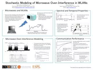
Motivation • Traditional radiometer architecture poor at rejecting RFI • “Low-level” RFI problematic in post-processing; difficult to distinguish from geophysical information • High amplitude but low duty cycle pulsed RFI (for example, microsecond radar pulses out of millisecond integration period) can appear as low-level RFI • Similarly, strong amplitude CW interferers can appear as low-level RFI • RFI localized in time and/or frequency can potentially be suppressed by simple time/frequency blanking methods • Traditional architecture can be retained by sampling data stream faster (0.1 to 1 msec) and adding analog sub-band channels; increases data rate; post-processing RFI removal, but can only go so far…. • Since 2002, a digital receiver based radiometer has been under development at Ohio State to implement such methods in real-time
Outline • System design • Implemented L-band prototype • Local experiments • Water pool observation • Radio astronomy observations
Detector LPF Design Concept • Traditional direct-detection radiometer • New design • Try to remove RFI in real time: clean data can still be integrated to retain low data rate Antenna Filter LNA ADC Digital Hardware RFI RFI Suppression/ Filtering/ Detection/Integration ADC Antenna Filter LNA Downconvert
Design including RFI Removal Stages (DIF) Low-noise front end Analog Downconverter Digital Downconverter Antenna ADC (APB) (FFT) Asynchronous Pulse Blanker 1024 point FFT Frequency domain blanker (not yet implemented) (SDP) Detection/ Integration Data Recording/ Control
NBLANK NWAIT Threshold NSEP APB algorithm • APB estimates mean/variance of incoming time domain signal; a sample > b standard deviations above the mean triggers blanker • Pre-detection samples can be blanked by including memory in the system, NWAIT parameter sets time period • “Blanked” samples replaced with zero; calibration effects can be corrected by scaling average power appropriately • Some FFT issues, but tests show minor
Frequency Domain Blanking • Post-FFT, two types of blanking can be considered • Time blanking of each FFT bin • Similar to original APB, but now at higher S/N • Implementation very similar to time-domain APB • Cross-frequency blanking • Requires some information on expected instrument passband • Can look for rapid changes in spectrum to indicate narrow-band RFI • Can also permanently blank certain bins known to contain RFI (for example hydrogen line emissions at L-band) • Again calibration effects can be corrected by keeping track of the number of blanked samples • Rapid frequency domain blanking of type #2 perhaps not required, since narrowband interferers vary slowly; still reduces data rate though
Outline • System design • Implemented prototype • L-band local experiments • Water pool observation • Radio astronomy observations
ADC Analog Devices 9410 DIF APB FFT SDP ADC 100 MSPS I/Q 200 MSPS Digital Back-End • Prototype samples 100 MHz, includes Digital IF downconverter (DIF), asynchronous pulse blanker (APB), FFT stage, and SDP operations • Implemented in FPGA’s for algorithm flexibility: • Altera "Stratix" parts: apprx 10000 LE, ~$260 each • A final prototype has been designed to combine processor components into one Stratix FPGA: apprx 30000 LE, ~$950 • Microcontroller interface via ethernet for setting on-chip parameters • Possible modes: • Direct capture of time domain data, sampled every 10 nsec • Integration, blanker on/off, integration lengths 0.01 to 21 msec • Max-hold, blanker on/off
ADC DIF/ APB FFT SDP Capture ADC Three FPGA Prototype • Modular form used for processor boards: note microcontrollers • EEPROM's on each card for autoprogramming of FPGA's on power-up
Outline • System design • Implemented prototype • L-band local experiments • Water pool observation • Radio astronomy observations
L-band Antenna/Front End Unit • Front end Tsys approx. 200K neglecting antenna Temperature control is critical to maintain internal standards; rest of system not temperature controlled
L-band Dual Channel Downconverter • One channel is ~1325-1375 MHz, other is ~1375-1425 MHz • Downconverter, digital receiver, computer, and thermal control systems in rack inside lab • High-compression point amplifiers used; isolators used to reduce channel coupling
Terminator Test of System Stability Terminator Spectra After ND Stabilization +0.25 dB 15 hrs -0.25 dB Sensitivity vs. Integration Total Power vs. Time
Height (m) Water Pool Observations • Experiments designed to demonstrate radiometric accuracy in the presence of interference • Observations of a large water tank; external cal sources are ambient absorbers and a sky reflector • Highly accurate ground-based radiometry is tough due to contributions from objects not under view, including reflections • Keep cal targets exactly the same size as pool to reduce these effects; observations of pool as ambient temp varies also • Initial tests in existing RFI, incl. air traffic control radar at 1331 MHz
Absorbers: Assume Tb=Tphys Reflectors: Assume Tb=Tref~Tsky? Water: Tb~Twat+QTref Pool and Cal Targets Still working toward obtaining absolutely calibrated data; Can still examine effectiveness of blanking strategies in uncalibrated data
Relative Power Variations: Pool Observation Blanker Off: H pol Blanker On: H pol 240 secs Noise Generator Terminator
Sky Observations • An alternate experiment was initiated using observations of the sky; a 3 m reflector was available – used same feed/front end • Sky observations at declination angles up to 30 degrees • Expect to see cold sky plus astronomical sources; minor atmospheric influence • Potential for using cold sky plus moon in a calibration • Initial results use software FFT’s and integration; low duty cycle as a result • 24 hour observations of astronomical sources
Sky Observation Results: Blanker on • Software FFT’s allow very high spectral resolution (~0.4 kHz); sufficient to observe Doppler shift of neutral Hydrogen line Hydrogen line emission around 1420 MHz; “S-curve” is due to Doppler shift associated with galactic region observed Elapsed Time (Hr) Moon
Relative Power Variations: Sky Observation APB Off APB On +.25 dB -.25 dB Radar contributions greatly decreased by APB
Conclusions • Digital receiver prototype developed and currently being applied in L-band water pool and sky observations • Base suppression algorithm is APB, followed by post-processing narrow band removal at present; can implement spectral processing in future hardware as well • Current data shows qualitative success of this approach, although continuing to work toward a final demonstration • Goal is to demonstrate well calibrated and stable brightness measurements even in the presence of RFI • We have also deployed this backend in aircraft observations at C-band, subject of next talk…..