Digital Receiver with Interference Suppression for Microwave Radiometry
270 likes | 497 Views
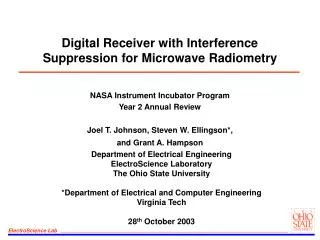
Digital Receiver with Interference Suppression for Microwave Radiometry. NASA Instrument Incubator Program Year 2 Annual Review Joel T. Johnson, Steven W. Ellingson*, and Grant A. Hampson. Outline. Slides 1-8: Administrative issues Slides 9-17: System development

Digital Receiver with Interference Suppression for Microwave Radiometry
E N D
Presentation Transcript
Digital Receiver with Interference Suppression for Microwave Radiometry NASA Instrument Incubator Program Year 2 Annual Review Joel T. Johnson, Steven W. Ellingson*, and Grant A. Hampson
Outline • Slides 1-8: Administrative issues • Slides 9-17: System development • Slides 18-23: Progress in experiments • Slides 24-26: LISA
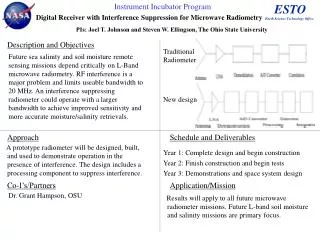
Instrument Incubator Program ESTO Earth Science Technology Office Digital Receiver with Interference Suppression for Microwave Radiometry PIs: Joel T. Johnson and Steven W. Ellingson, The Ohio State University Description and Objectives Traditional Radiometer Future sea salinity and soil moisture remote sensing missions depend critically on L-Band microwave radiometry. RF interference is a major problem and limits useable bandwidth to 20 MHz. An interference suppressing radiometer could operate with a larger bandwidth to achieve improved sensitivity and more accurate moisture/salinity retrievals. Antenna LNA Downconv. Corr/ ADC (optional) integrate New design LNA ADC Corr/Integrate Antenna Downconv. RFI Processor Approach Schedule and Deliverables A prototype radiometer will be designed, built, and used to demonstrate operation in the presence of interference. The design includes a processing component to suppress interference. Year 1: Complete design and begin construction Year 2: Finish construction and begin tests Year 3: Demonstrations and space system design Co-I’s/Partners Application/Mission Dr. Grant Hampson, OSU TRL levels: from 3 to 5/6 Results will apply to all future microwave radiometer missions. Future L-band soil moisture and salinity missions are primary focus.
Project Schedule • Project “year 1” was 9 months, 3/11/02-11/30/02
Progress in Year Two • Current Milestone: “Complete Breadboard Instrument Fabrication; Progress in Laboratory Tests” • Dual channel 100 MHz system completed (second prototype) • Temporal blanking strategy updated; progress in software RFI processor • Antenna, front end, downconverter integration complete • Experiments currently in progress • Addition: LISA system flown in AMSR-E "Wakasa bay" campaign; measured detailed L-band RFI information • Current TRL Status: In transition from TRL 3 to TRL 4
Budget/Personnel • Year 1 + Year 2 budget: 533.9K + 21K equipment • Remaining as of 9/30: ~50K + 0K equipment (25K/month in 2 mos) • No cost under- or over-runs are expected • Tentative budget for year 3: 288.9K • Personnel: • Co-Pis: J. T. Johnson, S. W. Ellingson • Lead Designer (Research Scientist): G. A. Hampson • RF Support (Research Scientist): Chi-Chih Chen • Technician: Jim Moncrief, Ray Feast • Graduate Students: Nakasit Niltawach (Graduated June 03), Al Hayslip (Graduated June 03), Noppasin Niamsuwan, Ranga Krisnamurchi • Undergrads: Mark Frankford, Ben Sinsheimer, Ryan Schultz, Miguel Lafleche • Document Server (password protected): http://esl.eng.ohio-state.edu/~swe/iip/docserv.html
Plans for 12/1/03-11/30/04 • 12/1/03-11/30/04: “Studies of space deployment and advanced algorithms; Larger scale observations” • Continue experiments to refine suppression algorithms • Perform tests in artificially generated RFI environments • Test/refine algorithms with data from LISA measurements • Develop basic design for space-borne system • Interim telecon review: April-May 2004 • last year 4/29/03 • Project supported by NPOESS IPO on use of system at C-band is currently in progress; recent briefing on project to Boeing Satellite Systems/IPO/Aerospace • First flight at C-band estimated as Spring 2004 • We’re interested in discussing possibilities for continuation of this work beyond this IIP project
Publications Recent Conference Presentations: • G. A. Hampson, S. W. Ellingson, and J. T. Johnson,"Design of an L-Band Microwave Radiometer with Active Mitigation of Interference," APS/URSI 2003, Columbus. • S.W. Ellingson, G.A. Hampson, and J.T. Johnson, "Design of an L-Band Microwave Radiometer with Active Mitigation of Interference", NASA ESTC. • S.W. Ellingson, G.A. Hampson, and J.T. Johnson, "Characterization of L-Band RFI and Implications for Mitigation Techniques", IGARSS 2003, Toulouse. • S.W. Ellingson, G.A. Hampson, and J.T. Johnson, "Design of an L-Band Microwave Radiometer with Active Mitigation of Interference", IGARSS 2003, Toulouse. • G. A. Hampson, S. W. Ellingson, and J. T. Johnson, “Design and Demonstration of an interference suppressing microwave radiometer,” submitted to IEEE Aerospace Conference, 2004. • Recent Internal Reports: • J. T. Johnson and S. W. Ellingson, “Airborne RFI Measurements using LISA during transit to and in the Wakasa Bay Campaign,” July 7, 2003. • S.W. Ellingson and J.T. Johnson, "Airborne RFI Measurements over the Mid-Atlantic Coast using LISA", Feb 10, 2003.
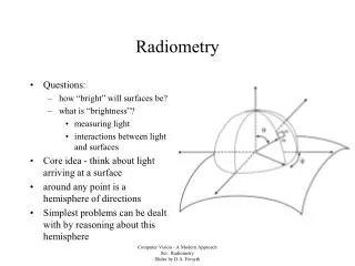
RFI Issues for Microwave Radiometers • A microwave radiometer is a sensitive receiver measuring naturally emitted thermal noise power within a specified bandwidth • Human transmission in many bands is prohibited by international agreement; these are the “quiet bands” ideal for radiometry • L-band channel quiet band is 1400-1427 MHz: larger bandwidth would improve sensitivity if RFI can be addressed. Ocean salinity missions require extremely high sensitivity. • Even within quiet band, RFI has still been observed - possibly due to filter limitations or intermodulation products • Many interferers are localized either in time or frequency: should be relatively easy to detect and remove with an appropriate system
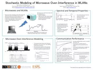
Pulsed interferer (~msec) Time Radiometer integration period (~msec) System Overview • Typical radiometer is a very “slow” instrument: power received is integrated up to msec scales by analog system before being digitized • Typical radiometer has a single, large bandwidth channel: susceptible to narrow band interference • Our design uses a digital receiver to allow much more rapid sampling of incoming data; this rapid sampling improves the ability to mitigate temporally localized RFI • Our design also performs a 1024 point FFT operation; improves ability to mitigate spectrally localized RFI • Processor must operate in real time so that final data rate can be reduced to a manageable level; implement processor in hardware (FPGA’s)
System Block Diagram Low-noise front end Analog Downconverter Digital Downconverter Antenna ADC Asynchronous Pulse Blanker 1024 point FFT Frequency domain blanker (not yet implemented) Integration Data Recording/ Control
Digital Back-End • System design includes digital IF downconverter (DIF), asynchronous pulse blanker (APB), FFT stage, and SDP operations • Dual channel implementation completed • Most blocks on separate boards to simplify testing and reconfiguration • Microcontroller interface via ethernet for setting on-chip parameters • Second prototype uses Altera "Stratix" FPGA’s: apprx 10000 LE, $260 • Designs for all components complete; DIF, APB, FFT, SDP, and capture card initial implementations functioning ADC Analog Devices 9410 DIF APB FFT SDP ADC 100 MSPS I/Q 200 MSPS
ADC DIF/ APB FFT SDP Capture ADC Current Digital Back-End Implementation • Modular form used for processor boards: note microcontrollers • EEPROM's on each card for autoprogramming of FPGA's on power-up
Improved APB algorithm • APB updates mean/variance of incoming time domain signal; a sample > b standard deviations above the mean triggers blanker • Previous design had only one “blanking timing register” (BTR); no detection of pulses with a blanking operation in progress • New design (green curves) has multiple BTR’s so pulse detection always possible; detections must be separated by NSEP • Calibration effects to be corrected in real-time by appropriate scale factors NBLANK NWAIT Threshold NSEP
Spectral Domain RFI Processing • A per-bin time domain blanking strategy similar to the APB can be implemented in the SDP component; higher SNR for better blanking • Cross frequency algorithms currently under investigation; basic idea is to search for regions of rapid change in spectrum • Testing these in software at the moment using integrated data; immense amount of data generated at full sample rate makes full test problematic • For true CW interferers, rapid temporal processing is not necessary; software scheme to throw out corrupted bins would be fine • Similar to algorithms used for analog sub-band radiometers (e.g. PSR C-band system) • Digital receiver gives capability of obtaining a large number of bins (here 1024) as opposed to only a few with analog sub-channels
Antenna/Front End Unit • Front end Tsys approx. 200K neglecting antenna Temperature control is critical to maintain internal standards; rest of system not temperature controlled Still experimenting with overall system stability
Dual Channel Downconverter • One channel is ~1325-1375 MHz, other is ~1375-1425 MHz • Downconverter, digital receiver, computer, and thermal control systems in rack inside lab • Working with system gain ~70 dB at present: moves –94 dBm in 100 MHz to –24 dBm; this triggers 4-5 ADC bits
Initial Results: Blanking a Dual Frequency Radar at Arecibo using the IIP Digital Receiver The radio telescope at Arecibo, PR suffers from RFI from distant ground-based air search radars 1325-1375 MHz spectra including digital IF, APB, FFT, and integration (42 msec) Before: ATC radar pulses visible After: APB removes radar
Height (m) Experiments at OSU • Experiments designed to demonstrate radiometric accuracy in the presence of interference • Observations of a large water tank; external cal sources are ambient absorbers and a sky reflector • Highly accurate ground-based radiometry is tough due to contributions from objects not under view, including reflections • Keep cal targets exactly the same size as pool to reduce these effects; observations of pool as ambient temp varies also • Initial tests in existing RFI; artificial RFI to be added as tests progress
Pool and Cal Targets • Water pool is approximately 16’ x 32’ by 6” deep; use saline water to decrease skin depth and eliminate sub-pool contributions • Absorbers are 12” (a few 18”) to cover the area; mounted on “racks” that can be placed on pool by a team of 2-4 people • Reflectors are foil covered foam • Temperature of pool, absorbers, and ground around pool all recorded; salinity of pool checked for each experiment
Absorbers: Assume Tb=Tphys Reflectors: Assume Tb=Tref~Tsky? Water: Tb~Twat+QTref Pool and Cal Targets Possible background contributions make precise calibration tough; data analysis to sort out these effects currently in progress
Results: System Stability • Observation of internal loads for approximately 10 hours; total power measurement, no RFI suppression • Gain varies appreciably for internal loads, due to uncontrolled cable and downconverter stages • Terminator result can be stabilized to <~0.01 dB over 10 hours through use of internal loads • Front end temperature controller still has 0.2K variation, plus strange 0.5K step; improvements here may improve stabilize further
Current Experiment Results • Hardware integration period 21 msec, switched every 1.33 secs through front end states, every 5 seconds through receiver mode Horizontally polarized data, absorber observation Radar at 1331 MHz apparent, along with other more CW RFI Blanker reduces radar effects, as well as saturation problems in FFT computation
Initial Calibrated Brightnesses • Initial results of experiment show promise, although spectral features needing correction are apparent; data shown includes software blanker RFI contributions still corrupt measurement even with blanker on Results with blanker off are similar, but further from model Real interest here is total power radiometry; need good spectral blanker for this Data at higher sample rate will improve software RFI suppression
LISA: L-Band Interference Surveyor/Analyzer S.W. Ellingson, J.T. Johnson, and G.A. Hampson, The Ohio State University Nadir-looking cavity-backed spiral antenna w/ custom LNA & calibration electronics in tail radome NASA’s P-3 Orion Research Aircraft Maiden LISA Flight: January 2, 2003 from Wallops Island, VA RF distribution, antenna unit control & coherent sampling subsystem Spectrum analyzer, electronics rack & control console mounted in cabin Examples of RFI observed at 20,000 feet LISA co-observes with existing passive microwave sensors to identify sources of damaging radio frequency interference (RFI) • 1200-1700 MHz using broadbeam spiral antenna • Spectrum analyzer for full-bandwidth monitoring of power spectral density • 14 MHz (8+8 bit @ 20 MSPS) coherent sampling capability for waveform capture and analysis • Flexible script command language for system control & experiment automation
LISA Wakasa Bay Campaign • LISA was deployed in the AMSR-E "Wakasa Bay" cal-val campaign; thanks to E. Kim and R. Austin (Co. State) for operations • Antenna in P-3 radome: high loss decreased sensitivity • On board, permanent RFI for frequencies <~1320 MHz • Problems with receiver compression in many cases; high loss helped! • Some software/control issues resulted in a few cases of data loss
LISA Results Summary • Campaign produced 8 GB of data: initial software developed to auto-detect large "pulses" > 200 stds above mean • Results sorted manually to find interferers localized in time/frequency • Numerous ARSR systems observed both in Japan and US; can correlate data versus ARSR position to examine range effects • Other radars also observed: chirped, varying pulse widths, multiple frequencies, etc. • Japanese data show some wideband channels, also a satellite downlink (1698 MHz); tests with these will challenge simple suppression algorithms • Detailed examination of 1411-1425 MHz channel shows numerous triggers, but signal properties are difficult to classify • Captures useful for testing effectiveness of suppression algorithms; will be used in space system design evaluation