Download
1 / 26
340 likes | 604 Views
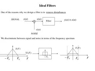
SIGNAL. Filter. NOISE. Ideal Filters. One of the reasons why we design a filter is to remove disturbances. We discriminate between signal and noise in terms of the frequency spectrum. Conditions for Non-Distortion

E N D
SIGNAL Filter NOISE Ideal Filters One of the reasons why we design a filter is to remove disturbances We discriminate between signal and noise in terms of the frequency spectrum
Conditions for Non-Distortion Problem: ideally we do not want the filter to distort the signal we want to recover. Same shape as s(t), just scaled and delayed. IDEAL FILTER Consequence on the Frequency Response: constant linear
For real time implementation we also want the filter to be causal, ie. since FACT (Bad News!): by the Paley-Wiener Theorem, if h(n) is causal and with finite energy, ie cannot be zero on an interval, therefore it cannot be ideal.
Characteristics of Non Ideal Digital Filters IDEAL Positive freq. only NON IDEAL
Two Classes of Digital Filters: a) Finite Impulse Response(FIR), non recursive, of the form With N being the order of the filter. Advantages: always stable, the phase can be made exactly linear, we can approximate any filter we want; Disadvantages: we need a lot of coefficients (N large) for good performance; b) Infinite Impulse Response(IIR), recursive, of the form Advantages: very selective with a few coefficients; Disadvantages: non necessarily stable, non linear phase.
Finite Impulse Response (FIR) Filters Definition: a filter whose impulse response has finite duration.
Problem: Given a desired Frequency Response of the filter, determine the impulse response . Recall: we relate the Frequency Response and the Impulse Response by the DTFT: Example: Ideal Low Pass Filter DTFT
Notice two facts: • the filter is not causal, i.e. the impulse response h(n) is non zero for n<0; • the impulse response has infinite duration. This is not just a coincidence. In general the following can be shown: If a filter is causal then • the frequency response cannot be zero on an interval; • magnitude and phase are not independent, i.e. they cannot be specified arbitrarily As a consequence: an ideal filter cannot be causal.
Problem: we want to determine a causal Finite Impulse Response (FIR) approximation of the ideal filter. rectangular window We do this by a) Windowing hamming window infinite impulse response (ideal) finite impulse response
Effects of windowing and shifting on the frequency response of the filter: a) Windowing: since then rectangular window hamming window
For different windows we have different values of the transition region and the attenuation in the stopband: Rectangular -13dB Bartlett -27dB Hanning -32dB Hamming -43dB Blackman -58dB attenuation with transition region
Effect of windowing and shifting on the frequency response: b) shifting: since then Therefore See what is For a Low Pass Filter we can verify the symmetry Then real forall . Then
The phase of FIR low pass filter: Which shows that it is a Linear Phase Filter. don’t care
Example of Design of an FIR filter using Windows: Specs: Pass Band 0 - 4 kHz Stop Band > 5kHz with attenuation of at least 40dB Sampling Frequency 20kHz Step 1: translate specifications into digital frequency Pass Band Stop Band Step 2: from pass band, determine ideal filter impulse response
Step 3: from desired attenuation choose the window. In this case we can choose the hamming window; Step 4: from the transition region choose the length N of the impulse response. Choose an odd number N such that: So choose N=81 which yields the shift L=40. Finally the impulse response of the filter
A Parametrized Window: the Kaiser Window The Kaiser window has two parameters: Window Length To control attenuation in the Stop Band
There are some empirical formulas: Attenuation in dB Transition Region in rad Example: Sampling Freq. 20 kHz Pass Band 4 kHz Stop Band 5kHz, with 40dB Attenuation
Then the impulse response of the FIR filter becomes ideal impulse response with
Impulse Response Frequency Response
Example: design a digital filter which approximates a differentiator. • Specifications: • Desired Frequency Response: • Sampling Frequency • Attenuation in the stopband at least 50dB. Solution. Step 1. Convert to digital frequency
Step 2: determine ideal impulse response From integration tables or integrating by parts we obtain Therefore
Step 3. From the given attenuation we use the Blackman window. This window has a transition region region of . From the given transition region we solve for the complexity N as follows which yields . Choose it odd as, for example, N=121, ie. L=60. Step 4. Finally the result
Frequency Response Impulse response h(n)