IP Addressing
IP Addressing. Internet Protocol: Which version?. There are currently two versions of the Internet Protocol in use for the Internet IPv4 Specified in 1980/81 (RFC 760, 791) Four byte addresses Universally deployed Problem : Address space almost exhausted IPv6

IP Addressing
E N D
Presentation Transcript
Internet Protocol: Which version? There are currently two versions of the Internet Protocol in use for the Internet • IPv4 • Specified in 1980/81 (RFC 760, 791) • Four byte addresses • Universally deployed • Problem: Address space almost exhausted • IPv6 • Specification from 1998 (RFC 2460) • Significant differences to IPv4, but not fundamental changes • 16-byte addresses • Problem: Not widely used (yet?)Google Study from Oct 2008: IPv6 available to 0.238% of users
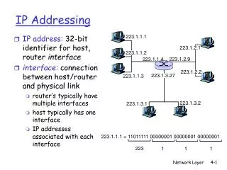
What is an IP Address? • IP address = Internet Protocol Version 4 address • 32-bit label for a network interface • Each interface has a separate IP address • On the public Internet, IP address is unique global address • The IP address is to used by hosts and routers for delivery of IP datagram • Important special cases: • Dynamically assigned IP addresses ( DHCP) • IP addresses in private networks ( NAT)
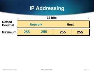
Dotted Decimal Notation • IPv4 addresses are written using dotted decimal notation • Each byte is identified by a decimal number in the range [0..255] • Example: 10000000 10001111 10001001 10010000 1st Byte = 128 2nd Byte = 143 3rd Byte = 137 4th Byte = 144 128.143.137.144
Structure of an IP address • IP address consists of a network prefix and a host number • Network prefix identifies a network • Host number identifies an interface on the network • How do we know how long the network prefix is? • The length of the network prefix is indicated • by a netmask, or • by a suffix given the length as a number (CIDR notation) • Netmask is often called subnetmask (there are subtle differences) network prefix host number
Notation of IP address • Example: • Network address is: 128.143.0.0 (or 128.143) • Host number is: 137.144 • Netmask is: 255.255.0.0 (or ffff0000) • Prefix or CIDR notation: 128.143.137.144/16 • Network prefix is 16 bits long 128.143 137.144
Network Prefix and Host Number • Each IP network (often called subnetwork or subnet) has an IP address: IP address of a network = Host number is set to all zeros, e.g., 128.143.0.0 • IP routers are devices that forward IP datagrams between IP networks • Delivery of an IP datagram proceeds in 2 steps: • Use network prefix to deliver datagram to the right network • Once the network is found, use the host number to deliver to the right interface
How does one get an IP network address? • IP address allocation is managed by five Regional Internet Registries (RIR) • Each RIR manages ranges of addresses: http://www.iana.org/assignments/ipv4-address-space/ipv4-address-space.xml
Special IP Addresses • Special addresses: Loopback interfaces • all addresses 127.0.0.1-127.0.0.255 are reserved for loopback interfaces • Most systems use 127.0.0.1 as loopback address • loopback interface is associated with name “localhost” IP address of a network • Host number is set to all zeros, e.g., 128.143.0.0 Broadcast address • Host number is all ones, e.g., 128.143.255.255 • Broadcast goes to all hosts on the network • Often ignored due to security concerns • Test / Experimental addresses Certain address ranges are reserved for “experimental use”. Packets should get dropped if they contain this destination address (see RFC 1918): 10.0.0.0 - 10.255.255.255 172.16.0.0 - 172.31.255.255 192.168.0.0 - 192.168.255.255 • Convention (but not a reserved address) Default gateway has host number set to ‘1’, e.g., e.g., 192.0.1.1
Subnetting UofT Network • Scenario: Organization has a large network prefix and wants to delegate management of IP addresses • Subnetting: Use a portion of the host name to identify a smaller network ( “subnetwork”, “subnet”). • Each subnets is a separate IP network 128.100.0.0/16 Faculty of Engineering Faculty of A&S 128.100.58.0/24 128.100.11.0/24 Library 128.100.136.0/24
Basic Idea of Subnetting • Split the host number portion of an IP address into a subnet number and a (smaller) host number. • Result is a 3-layer hierarchy • The extended network prefix is also called subnetmask • Then: • Subnets can be freely assigned within the organization • Internally, subnets are treated as separate networks • Subnet structure is not visible outside the organization network prefix host number network prefix subnet number host number extended network prefix
Subnetmask • Routers and hosts use an extended network prefix (subnetmask) to identify the start of the host numbers
Example: Subnetmask • 128.143.0.0/16 is the IP address of the network • 128.143.137.0/24 is the IP address of the subnet • 128.143.137.144 is the IP address of the host • 255.255.255.0 (or ffffff00) is the subnetmask of the host • When subnetting is used, one generally speaks of a “subnetmask” (instead of a netmask) and a “subnet” (instead of a network)
Advantages of Subnetting • With subnetting, IP addresses use a 3-layer hierarchy: • Network • Subnet • Host • Reduces router complexity. Since external routers do not need to know about subnetting, the complexity of routing tables at external routers is reduced. • Note: Length of the subnet mask need not be identical at all subnetworks.
Creating and Managing Subnetting • Use of subnetting or length of the subnetmask is decided by the network administrator, who acts as owner of • Subnets are created by setting the subnetmask of an IP interface • Important: Subnetmasks must be set consistently
No Subnetting • All hosts think that the other hosts are on the same network
With Subnetting • Hosts with same extended network prefix belong to the same network
With Subnetting • Different subnetmasks lead to different views of the scope of the network
Classful IP Addresses and CIDR • In 1993, there was a major shift for interpreting and allocating IP addresses: until 1993: ClassfulAddresses after 1993: CIDR = Classless Interdomain Routing
Classful IP Addresses • When Internet addresses were standardized (early 1980s), the Internet address space was divided up into classes: • Class A:Network prefix is 8 bits long • Class B:Network prefix is 16 bits long • Class C:Network prefix is 24 bits long • Class D: Used (multicast) group addresses • Class E: Reserved • Each IP address contained a key which identifies the class: • Class A:IP address starts with “0” • Class B:IP address starts with “10” • Class C:IP address starts with “110” • No need for netmasks (unless subnetting is used)
Classful IP Addresses • We will learn about multicast addresses later in this course.
IP Allocation with Classful IP Addresses • Limited flexibility for obtaining a network address: ≤ 254 IP addresses: Class C ≤ 216-1 = 65534 IP addresses: Class B ≤ 224-1 = 16,772,214 IP addresses: Class A • Too few network addresses for large networks 27 = 128 Class A networks 214 = 16,384 Class B networks • Flat address space. Routing tables in the backbone Internet need one entry for each network address. Class C networks: up to 221 = 2,097,152 entries By 1993, the lookup time of routing tables had become a bottleneck for Internet performance
CIDR - Classless Interdomain Routing • Goals: • New interpretation of the IP address space • Restructure IP address assignments to increase efficiency • Enable routing table aggregation to minimize route table entries • CIDR (Classless Interdomain Routing) • Abandons the notion of classes • Key Concept:The length of the network prefix in the IP addresses is kept arbitrary • Consequences: • Size of the network prefix must be provided with an IP address ( CIDR notation of IP addresses) • Hierarchical routing aggregation introduces dependency of IP addresses to service provider • Need for new lookup algorithms for routing tables
CIDR Notation • CIDR notation of an IP address: 192.0.2.0/18 • "18" is the prefix length. It states that the first 18 bits are the network prefix of the address (and 14 bits are available for specific host addresses) • CIDR notation can replace the use of subnetmasks (but is more general) • IP address 128.143.137.144 and subnetmask 255.255.255.0 becomes 128.143.137.144/24 • CIDR notation allows to drop traling zeros of network addresses: 192.0.2.0/18 can be written as 192.0.2/18
CIDR address blocks • CIDR notation can nicely express blocks of addresses • Blocks are used when allocating IP addresses for a company and for routing tables (route aggregation) CIDR Block Prefix # of Host Addresses /27 32 /26 64 /25 128 /24 256 /23 512 /22 1,024 /21 2,048 /20 4,096 /19 8,192 /18 16,384 /17 32,768 /16 65,536 /15 131,072 /14 262,144 /13 524,288
Subnetting and Supernetting • CIDR is compatible with subnetting: • Subnets are created by extending the prefix • CIDR can do more: • CIDR can refer to multiple networks with a single prefix: • 128.143.0.0/16 and 128.142.0.0/16 can be summarized as 128.142.0.0/15 • This is called supernetting (In fact, CIDR and supernetting are often used as the same thing) • If neighboring networks have similar address blocks, supernetting reduces the size of routing tables
CIDR and Hierarchical IP address allocation • Exploiting supernetting to reduce size of routing tables: • Backbone ISPs obtain blocks of IP addresses and allocate portions of their address blocks to their customers • Customers can allocate a portion of their address block to their own customers
Hierarchical Structure of IP Addresses Company Y : ISP X owns: 128.100/16 Rest of Internet ISP Z : Organization A: Organization B:
Hierarchical Structure of IP Addresses Company Y : 128.100.2/24 ISP X owns: 128.100/16 Obtained from ISP X Obtained from ISP X Rest of Internet ISP Z : 128.100.11/24 Obtained from ARIN Obtained from ISP Z Obtained from ISP Z Organization A: 128.100.11.192/26 Organization B: 128.100.11.64/26
Hierarchical Structure of IP Addresses Company Y : 128.100.2/24 ISP X owns: 128.100/16 Rest of Internet Routing table entry for 128.100.2/24 and 128.100.11/24(no entry for 128.100.11.192/26 and 128.100.11.64/26. ISP Z : 128.100.11/24 Only one routing entry for 128.100/16No entries needed for network addresses of Company Y, ISP Z, or Organizations A, B. Organization A: 128.100.11.192/26 Organization B: 128.100.11.64/26
Drawback of Hierarchical IP Addresses • IP address assignment depends on service provider Company Y : 128.100.2/24 ISP X owns: 128.100/16 Rest of Internet ISP Z : 128.100.11/24 Must change IP addresses when changing service provider Organization A: 128.100.11.192/26 Organization B: 128.100.2.64/26 128.100.11.64/26
CIDR and Routing Tables • Aggregation of routing table entries: • 128.100.0.0/16 and 128.101.0.0/16 can be represented as 128.100.0.0/15 • Longest prefix match: Routing table lookup finds the routing entry that matches the the longest prefix What is the outgoing interface for 128.143.137.0/24 ? Route aggregation can be exploited when IP address blocks are assigned in an hierarchical fashion Routing table
IPv6 - IP Version 6 • IP Version 6 • Is the successor to the currently used IPv4 • Specification completed in 1994 • Makes improvements to IPv4 (no revolutionary changes) • One (not the only !) feature of IPv6 is a significant increase in of the IP address to 128 bits (16 bytes) • IPv6 will solve – for the foreseeable future – the problems with IP addressing • 1024 addresses per square inch on the surface of the Earth.
IPv6 vs. IPv4: Address Comparison • IPv4has a maximum of 232 4 billion addresses • IPv6 has a maximum of 2128 = (232)4 4 billion x 4 billion x 4 billion x 4 billion addresses
Notation of IPv6 addresses • Convention: The 128-bit IPv6 address is written as eight 16-bit integers (using hexadecimal digits for each integer) CEDF:BP76:3245:4464:FACE:2E50:3025:DF12 • Short notation: • Abbreviations of leading zeroes: CEDF:BP76:0000:0000:009E:0000:3025:DF12 CEDF:BP76:0:0:9E :0:3025:DF12 • “:0000:0000:0000” can be written as “::” CEDF:BP76:0:0:FACE:0:3025:DF12 CEDF:BP76::FACE:0:3025:DF12 • IPv6 addresses derived from IPv4 addresses have 96 leading zero bits. Convention allows to use IPv4 notation for the last 32 bits. ::80:8F:89:90 ::128.143.137.144