Download
1 / 71
2.25k likes | 7.3k Views
Plastic solar cells. M. A. Loi Zernike Institute for Advanced Materials University of Groningen, The Netherlands e-mail M.A.Loi@rug.nl. Overview. 1 st hour Solar cells in general Solar Radiation p-n junction The organic version 2 nd hour Improving plastic solar cells

E N D
Plastic solar cells M. A. Loi Zernike Institute for Advanced Materials University of Groningen, The Netherlands e-mail M.A.Loi@rug.nl
Overview 1st hour • Solar cells in general • Solar Radiation • p-n junction • The organic version 2nd hour • Improving plastic solar cells • Low band-gap polymers • Charge transfer states is detrimental?
Solar Cells I • Long duration power supply • Satellites • Space vehicles • Remote locations on earth • Valid alternative to fossil fuels • Pollution free
Solar Cells II • Photovoltaic effect • Becquerel (1839) • Fritts {Selenium} (1883) • Ohl {semiconductor junction solar cell}(1946) • Chapin, Fuller, Person {Silicon p-n junction solar cells} (1954)
Motivations • ENERGY Increasing energy need Exhaustion of fossil fuels Diversification of energy sources Energy for all (2 billion people without electricity) • ECOLOGY Pollution of environment CO2 Responsible Climate change • ECONOMY Energetically independent
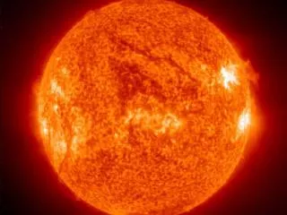
Solar Radiation • Every second in the sun 6 x 10¹¹ kg H2 → He + 4 x 10²⁰ J ☼ • At the average distance of the earth the solar radiation is 1353 W/m2 • The atmosphere attenuates the solar radiation • Absorption water - IR • Absorption Ozone – UV • Scattering Air Mass
Air Mass • Air mass = the path length of the light from a celestial source relative to that at the zenith at sea level. • increases as the angle between the source and the zenith increases (AM38 at the horizon). • Out of the atmosphere AM0 • On earth surface with sun at the zenith AM1 • Average for terrestrial applications - 45˚ from the zenith AM1.5 AM= sec qq = zenith angle
Solar cells – inorganic case • Single bandgap material • Photons with hn<Eg lost energy • Photons with hn=Eg used energy • Photons with hn>Eg (hn-Eg) lost energy Illuminated p-n junction
Ideal solar cell IL current produced by solar radiation Is diode saturation current RL load resistance Shockley diode equation A device area
IV characteristics Short circuit current Open circuit voltage
IV characteristics-realistic Series resistance Junction, impurity concentration Shunt resistance – leakage current
IV characteristics-realistic Rs in Si solar cells 0.7-0.4 W The effect RSH is negligible
Conversion efficiency • FF; IL; Voc should be maximized for efficient solar cells! Fill factor Conversion efficiency EQE or IQE, quantum efficiency-percentage of photon converted in carriers (ISC)
Plastic Solar cells 2000 2008
Pro & con Advantages • tailoring of opto-electronic properties • large areas • low temperatures (RT) • processing from solution • roll to roll manufacturing • light weight • transparent • low cost…….maybe… Power paint?
Pro & con Problems • low ambient stability • strongly bound excitons (Frenkel like) • Exciton diffusion length rather short 5-20 nm. • low mobility of charge carriers • μn (c-Si) > 1000 cm2/Vs • μh (polymer) ≈ 0.1 cm2/Vs • difficult to obtain low band-gap materials
Nevertheless http://www.konarka.com Disposable low-end applications!
To start - photoexcitations Charge Transfer exciton Frenkel exciton Stronghly bound (0.4 eV in PPV); radius 5 Å Molecola + - - + Polarons • Molecular semiconductors • coulomb interaction • elettron-phonon coupling + -
Intermolecular excitons Frenkel excitons non radiative states Triplet excitons Non radiative-emission Fluorescence Phosphorescence Ground state
The first examples • Early works inspired by nature (photosynthesis) • Porphyrins, phthalocyanines, perylenes (xerography), merocyanines • Organic heterojunction devices: p-type / n-type organic semiconductors • – 1970’s until 1995: organic heterojunction bilayers • – 1985 Tang cell: PTCBI (45 nm) and CuPc (25 nm) • 1% efficiency
The Kodak approach Tang et al., APL 2005
The polymer approach! • Active layer: bulk heterojunction - hole conducting material - electron conducting material • Operation principle: • Exciton photoexcitation • Diffusion of the excitons towards the organic-organic interface • Charge separation/electron transfer • Transport of charge carriers towards the electrodes
Photoinduced Charge Generation An ultra-fast e- transfer occurs between Conjugated Polymer / Fullerene composites upon illumination. The transition time is less than 40 fs. Back transfer very slow! ms - ms ACCEPTOR DONOR exciton MDMO PPV 3,7 - dimethyloctyloxy methyloxy PPV PCBM 1-(3-methoxycarbonyl) propyl-1-phenyl [6,6]C61 N. S. Sariciftci et al., Science 258, 1474 (1992)
The driving force! • Electron affinity fullerene derivatives! -3.5 eV -4.2 eV -5.2 eV -6 eV PCBM Polymer
Bulk Heterojunctions e- Al Electrode Al Electrode e- e- e- P+ e- e- e- e- P+ ITO on Glass / Plastic MDMO-PPV PCBM hn
P-Solar Cells - FILM PREPARATION Spin Casting is a easy coating technique for small areas. Material loss is very high. Doctor Blade Technique was developed for large area coating Doctor Blade has no material loss
Production - Large Area Large Area Thin Film Production using Doctor/Wire Blading a) b)
Plastic Solar Cells - CONTACTING The cathode electrode is applied by evaporation. Different electrodes are used for different applications. Sealing is absolutely necessary for an increased life time of plastic solar cells.
Bulk Heterojunctions e- Al Electrode Al Electrode e- e- e- P+ e- e- e- e- P+ ITO on Glass / Plastic MDMO-PPV PCBM hn
The morphology issue… 2,5% < 1% S. E. Shaheen, Appl. Phys. Lett., 78, 841–843 (2001)
Now.. Organic solar cells performances depend on the material properties and microscopic structure of the bulk heterojunction! P3HT 4,5-5.0 % > 60 polymers checked last 5 years!
Optimization heff = Isc * Voc * FF / Iinc Isc Tuning of the Transport Properties - Mobility VocTuning of the Electronic Levels of the Donor Acceptor Systems FF Tuning of the Contacts and Morphology Iinc Tuning of the Spectral Absorbance/Absorbing more light (low bandgap)
Organic Solar cells bulk heterojunction 3D heterostructure hole conducting material + electron conducting material bulk heterojunction PCBM (acceptor) Polymer (donor) Power conversion efficiency ~ 5 - 6%
Remember-Organic Solar Cells • Working mechanism-steps • Excitons photoexcitation • Diffusion of the excitons towards the interface • Charge separation/electron transfer • Transport of charge carriers towards the electrodes • Organic solar cells performances depend on • the material properties • the microscopic structure of the bulk hetero-junction
The driving force! • Donor and acceptor LUMO energy offset! -3.5 eV -4.2 eV -5.2 eV -6 eV PCBM Polymer Ultrafast phenomena!
Enhancing devices efficiency • Optimize the materials properties • Matching solar spectrum! NIR materials • Relative position of the energy levels of the donor and acceptor • optimal offset between LUMO (D) – LUMO(A) for electron transfer at least 0.3 – 0.5 eV • P3HT:PCBM: LUMO (D) –LUMO(A) ~1.1 eV • Optimize the morpholog • microscopic phase separation ( exciton diffusion length ~ 5 – 7 nm ) • presence of a percolation pathway
Remember-Solar cells parameters • JSC– short-circuit current • Jph– photocurrent • FF– fill factor: • VOC – open circuit voltage LUMO (D) 3 LUMO (A) 4 Donor Voc • h - power conversion efficiency Energy (eV) Acceptor HOMO (D) 5 6
bisPCBM Power conversion efficiency ~ 4.5 % !!! 3 P3HT:PCBM 4 Donor Voc • LUMO offset ~ 1.0 eV • Voc~ 0.73 V Acceptor 5 • power conversion efficiency ~ 3.8 % • LUMO offset ~ 1.1 eV • Voc~ 0.59 V 6 The reduction of the LUMO offset Energy(eV) M. Lenes et al, Adv. Mater.2008, 20, 2116
PL of thermally annealed films The devices performance: P3HT:PCBM – 3% P3HT:bisPCBM – 3.6% P3HT:bisPCBM –tPL ≈ 60 ps P3HT:PCBM –tPL ≈ 41 ps electron transfer is more efficient for P3HT:PCBM
PL of solvent annealed films The devices performance: P3HT:PCBM – 3.8% P3HT:bisPCBM – 4.6% P3HT:bisPCBM –tPL ≈ 38 ps P3HT:PCBM –tPL ≈ 31 ps electron transfer is more efficient for P3HT:PCBM
AFM measurements P3HT:PCBM P3HT:bisPCBM • surfaces is smoother for samples prepared by thermal annealing • difference in RMS roughness between P3HT:PCBM and P3HT:bisPCBM 3.9 nm 4.6 nm spin coated 10.7 nm 12.4 nm slow dried 10x10mm