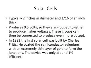
Solar Cells
Solar Cells. Outline . Single-Junction Solar Cells . Multi-Junction Solar Cells. Conduction in nanostructured materials (with Voltage applied). Conduction in nanostructured materials. electron. Biased Semiconductor as a Photodetector of Light. CONDUCTION BAND. electron. VALENCE BAND.

Solar Cells
E N D
Presentation Transcript
Solar Cells Outline . Single-Junction Solar Cells . Multi-Junction Solar Cells
Conduction in nanostructured materials (with Voltage applied) Conduction in nanostructured materials electron
Biased Semiconductor as a Photodetector of Light CONDUCTIONBAND electron VALENCEBAND METAL CONTACT hole (electron vacancy) A METAL CONTACT 1. Photon can excite an electron from Valence Band (ground state) to Conduction Band (excited state) 2. The externally applied bias (that generates the electric field in the semiconductor) will separate the photo-generated electron and hole 3. The electron and a hole will reach the metal contacts, be collected by the bias battery, and be measures as a photocurrent. 4. If more photons are absorbed by the semiconductor, more current we will measured
PHOTODETECTORS Apply bias (spend energy) to measure photocurrentgenerated by light shining on the photodetector SOLAR CELLS Shine light on the solar cell and generate voltage and current (power, energy)
Resistor A V (junction of two different semiconductors) Semiconductor Heterojunction Solar Cell MATERIAL A MATERIAL B IT IS ENERGETICALLY FAVORABLE FOR ELECTRONS TO GO TO THE MATERIAL ON THE RIGHT electron CONDUCTIONBAND IT IS ENERGETICALLY FAVORABLE FOR HOLES TO STAY IN THE MATERIAL ON THE LEFT VALENCEBAND METAL CONTACT METAL CONTACT hole 1. Photon can excite an electron from Valence Band (ground state) to Conduction Band (excited state) 2. At the heterojunction the electron and hole can separate, resulting in buld-up of electrons on the right and build-up of holes on the left WE GENERATED PHOTOVOLTAGE 3. If solar cell is connected to a resistor, the photo-voltage will drive current through the resistor
Solar Cell Characteristics I Circuit model RS VOC dark IL RP V Maximum power rectangle light ISC Critical parameters: VOC, open circuit voltage ISC, short circuit current FF, fill factor = area max. power rectangle VOC . ISC
50 40 30 20 10 0 Fundamental Efficiency Limits of Solar Energy Conversion in Photovoltaics Excess energy above Eg heat MAXIMUM POWER CONVERSION EFFICIENCY PREDICTED FOR A HOMOJUNCTION SEMICONDUCTOR SOLAR CELL WITH VOC = Eg Conduction band AM1.5 300K GaAs Si Eg = max. VOC Power Conversion Efficiency (%)[(generated electrical power)/(solar power) x100] Ge CdS Valence band 0 1 2 3 Eg(eV) As band gap increases, the maximum open circuit voltage increases, but the fraction of the solar spectrum absorbed decreases.
Multiple Junction Cells Connect solar cells in series. Usually wide gap cells in series with narrow gap cells. recombination interface EC 0.95 eV 1.6 eV EV High energy gap Low energy gap Voltage of cells adds. But need same current through each cell. Must carefully tune absorption. Advantage: highest performance cells made this way.
from M. Baldo A SHORT TERM GOAL: SOLAR CONCENTRATORS FIXED LENS OR MIRROR COLLECTOR • Concentration factor limited to n2. (G ~ 2) (n: refractive index) Efficiency of devices increases with light intensity: - Short circuit current increases linearly with incident power - Open circuit voltage increases Image is in the public domain TRACKING COLLECTORS • Mechanical – adds cost and maintenance • PV needs cooling • Must be widely spaced to avoid shadowing Cooled cell Slide courtesy of Marc Baldo. Used with permission.
from M. Baldo air solar radiation glass dye PV PV air A different approach: use Organics only for Optical Function of solar cells … Simple construction: dye in or on waveguide photoluminescence Structure collects and concentrates light onto PV cells. This is not a new idea… ‘LUMINESCENT SOLAR CONCENTRATOR’ W. H. Weber and J. Lambe, Applied Optics 15, 2299 (1976) Slide courtesy of Marc Baldo. Used with permission.
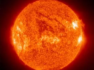
ONE YEAR OF SOLAR ENERGY PROVIDED BY SUN ONE YEAR OF EARTH’S FOSSIL ENERGY CONSUMPTION x 10,000 = SOLAR ENERGY = RENEWABLE RESOURCE
Deployment of Solar Photovoltaics in U.S. 2,800 Gwepeak is the PV deployment level at which 2008 U.S. electricity production levels are offset 10% of U.S. electricity BY 2022 WE COULD DEPLOY PVs TO OFFSET 10% OF U.S. ELECTRICITY DEMANDFOR LARGER DEPLOYMENTS – STORAGE TECHNOLOGY IS NEEDED
Annual Purchasing Power Parity (PPP) in $US Population In Millions 4 Billion People Earning less than $2,000/year Middle Class in developing countries Wealthy Nations 100 > $20,000 $2,000—$20,000 2,000 < $2,000 4,000 “The Bottom of the Pyramid” Source: Prahalad & Hammond,Harvard Business Review, Vol. 80, Issue 9 (Sep. 2002), pp48-58
Solar Cookers All images are in the public domain
MIT OpenCourseWare http://ocw.mit.edu 6.007 Electromagnetic Energy: From Motors to Lasers Spring 2011 For information about citing these materials or our Terms of Use, visit: http://ocw.mit.edu/terms.