MONALISA update
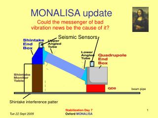
Seismic Sensors. beam pipe. Shintake interference patter. MONALISA update. Could the messenger of bad vibration news be the cause of it?. Overview. Goal of ATF2 installation: Test if MONALISA vacuum system introduces vibrations onto Shintake monitor

MONALISA update
E N D
Presentation Transcript
Seismic Sensors beam pipe Shintake interference patter MONALISA update Could the messenger of bad vibration news be the cause of it? Stabilization Day 7 Oxford MONALISA
Overview • Goal of ATF2 installation: Test if MONALISA vacuum system introduces vibrations onto Shintake monitor • Installation of MONALISA vacuum system at ATF2 • Minimal Force system • Motion Stability during pump down measured by KEK survey team • Vibration Measurements of LAPP group • Fringe stability test done by Shintake group (Tokyo University) Stabilization Day 7 Oxford MONALISA
Good progress • We kept within our proposed schedule • As set out in ATF2 meeting 17 Jun 09 • All items arrived at KEK 1st July 2009 • Brought to ATF2 roof within 15 mins of arrival • On ATF2 roof • System assembled and retested • Brought to ATF2 Final focus tunnel • Reassembled at IP Thursday 9th July and tested Stabilization Day 7 Oxford MONALISA
On the roof of the ATF2 Stabilization Day 7 Oxford MONALISA
Schematic Layout of Pneumatics • Vacuum in end boxes connected through inner bellows • High pressure only connected to outer bellows chamber Stabilization Day 7 Oxford MONALISA
Sensor readout during pumping Stabilization Day 7 Oxford MONALISA
Into the ATF2 tunnel Stabilization Day 7 Oxford MONALISA
The DBS was hoisted into place Full assembly completed well within one day Stabilization Day 7 Oxford MONALISA
DBS pumped out: with rods in • Reached 28 Pa with a different pump • vacuum integrity was unaltered Stabilization Day 7 Oxford MONALISA
Tilt sensor • Tilt change on Shintake ~5+5 mrad • After MONALISA DBS installed at IP Stabilization Day 7 Oxford MONALISA
Forces measured pumping down when mounted at ATF2 IP Regulator cycle ~225 s Stabilization Day 7 Oxford MONALISA
(x,y,z) Physicists coordinates • In the following we’re using the physicists coordinate frame Y Z X Stabilization Day 7 Oxford MONALISA
Tracking QD0 motion in Z • Set MONALISA at operational pressure • Pumped out vacuum vessel • Over-pressure in outer bellowed chamber • Set up independent tracking of QD0 • Used FARO to survey QD0 position changes • Keyence laser meter tracked QD0 mounted on SD0 base plate Stabilization Day 7 Oxford MONALISA
KEYENCE tracking QD0 Z QD0 KEYENCE Readout sensor in mV 10 V = 5 mm 1 mV = 0.5 mm Readout with our ADC/LabVIEW DAQ Supported from SD0 Stabilization Day 7 Oxford MONALISA
FARO survey instrument Retro FARO Stabilization Day 7 Oxford MONALISA
Comparison of FARO & KEYENCE Stabilization Day 7 Oxford MONALISA
Tracking QD0 motion in Z Stabilization Day 7 Oxford MONALISA
Tracking QD0 motion in X Stabilization Day 7 Oxford MONALISA
Left-right QD0 mover tests Stabilization Day 7 Oxford MONALISA
Left-right QD0 mover tests Stabilization Day 7 Oxford MONALISA
Left-right QD0 mover tests DBS spring constant is small enough to let QD0 move freely Stabilization Day 7 Oxford MONALISA
What to learn from this measurements? • We are told that static tolerances for QD0: • 100μm in x,y,z • Our measurements show that even with the current pressure control system we meet this tolerance. • The low spring constant of the DBS allows the QD0 mover to move the magnet unhindered. • Dynamic tolerances: vertical: 10 nm, (between Shintake and QD0) horizontal: 500 nm along beam: 10 μm Stabilization Day 7 Oxford MONALISA
Vibration Measurements performed by Benoît BOLZON (LAPP) taken from talk presented at ATF2 meeting July 15. 1. Relative motion calculation using representative absolute motion 2. Impact of Monalisa on vibrations (3 directions) between: - Shintake and QD0 with and without pressure - QD0 and QF1 with pressure Comparison of measurements with/without Monalisa Measurements without MONALISA have been repeated two weeks ago with cooling water flowing inside FD 3. Conclusion Stabilization Day 7 Oxford MONALISA
Choice of a representative ground motion measured at ATF2 • Choice of a high ground motion during shift period • Friday 12/12/08 at 3pm • Above 0.2Hz: 218nm • Above 1Hz: 128nm • Amplitude almost the same during 4 hours of shift • Choice of ground motion at 3pm representative • Relative motion calculation by taking this ground motion PSDgm Stabilization Day 7 Oxford MONALISA 24
Impact of Monalisa on vibrations between: • - Shintake and QD0 with and without pressure • - QD0 and QF1 with pressure • Comparison of measurements with/without Monalisa Vibration measurements between Shintake and QD0 Vibration measurements between QD0 and QF1 Stabilization Day 7 Oxford MONALISA 25
Vibration transmission between Shintake and QD0 Vertical direction • Almost same coherence: • - With/without Monalisa • - With/without pressure • Only difference: QD0 resonance slightly lower due to Monalisa weight • - No Monalisa: 65.3Hz • - With Monalisa: 60.3Hz • With Monalisa: Same transfer function with/without pressure Stabilization Day 7 Oxford MONALISA 26
Vibration transmission between Shintake and QD0 Vertical direction • Below 4Hz: increase of relative motion due to not enough high SNR • (coherence very close to 1: relative motion should not increase) Relative motion above 4Hz (should be the same than above 0.1Hz) : • Relative motion above 4Hz: • - No Monalisa: 5.0nm • - Monalisa with pressure: 5.7nm • - Monalisa without pressure: 5.8nm Almost no change compared to tolerances Stabilization Day 7 Oxford MONALISA 27
Vibration transmission between Shintake and QD0 Direction parallel to the beam • Almost same coherence: • - With/without Monalisa • - With/without pressure • Only difference: QD0 resonance slightly lower due to Monalisa weight • - No Monalisa: 18.0Hz • - With Monalisa: 16.6Hz • With Monalisa: Same transfer function with/without pressure Stabilization Day 7 Oxford MONALISA 28
Vibration transmission between Shintake and QD0 Direction parallel to the beam • Same relative motion with/without Monalisa (even better with Monalisa above 7Hz) • Same relative motion with/without pressure in Monalisa Stabilization Day 7 Oxford MONALISA 29
Vibration transmission between Shintake and QD0 Direction perpendicular to the beam • Almost same coherence: • - With/without Monalisa • - With/without pressure • QD0 resonance almost the same: • - No Monalisa: 20.4Hz • - With Monalisa: 19.2Hz • SM resonance higher with Monalisa (59.6Hz 55.0Hz): good! • With Monalisa: Same transfer function with/without pressure Stabilization Day 7 Oxford MONALISA 30
Vibration transmission between Shintake and QD0 Direction perpendicular to the beam • Same relative motion with/without Monalisa (even better with Monalisa above 10Hz) • Same relative motion with/without pressure in Monalisa Stabilization Day 7 Oxford MONALISA 31
Vibration transmission between QD0 and QF1 Vertical direction • Without Monalisa: QD0/QF1 resonances almost do not appear (very thin peak) since: • their frequencies are almost the same • QD0/QF1 move in phase (very close to each other) • With Monalisa: QD0 and QF1 resonances slightly appear (factor 5) since QD0 resonant frequency is slightly lower (due to Monalisa weight) Stabilization Day 7 Oxford MONALISA 32
Vibration transmission between QD0 and QF1 Vertical direction • Relative motion increase of 2nm with Monalisa due to QD0/QF1 resonances (decrease of QD0 resonant frequency) : very low! • Solution: put a mass on QF1 to decrease its resonant frequency down to QD0 resonant frequency Stabilization Day 7 Oxford MONALISA 33
With GM/flowing cooling water, relative motion of SM to QD0: • Tolerances still achieved with Monalisa (almost no influence) • N.B: No influence of the regulation system • With GM/flowing cooling water, relative motion of QF1 to QD0: This is not an issue!! • In vertical direction: almost no influence of Monalisa • In horizontal directions: still acceptable because of the large tolerances • A solution: put a mass on QF1 to get same resonances than QD0 ones 34 Stabilization Day 7 Oxford MONALISA
Phase StabilityTaken from the talk presented by T. Yamanaka at ATF2 meeting 15 July 09 Measure fringe phase stability indirectly off the IP and get the information about the IP fringe • Motivation • Shintake monitor uses laser interference fringe pattern to measure beam size. • It is important to know the stability of the fringe position ( = fringe phase). • However, it is impossible to measure it at the IP Stabilization Day 7 Oxford MONALISA
Phase Stability Measurement Calculate the phase at the peak frequency Make interference fringe again on the lens and Magnify Fouriertransform and get the peak frequency Microscope Lens IP Linear Image Sensor Measure fringe profile Schematic of Phase Monitor Stabilization Day 7 Oxford MONALISA
Measurement for MONALISA • Phase stability is the key of the Shintake monitor • Checked the effect of the MONALISA system • without MONALISA • MONALISA is mounted on the Shintake monitor table and QD0, double bellows system is activated • MONALISA is mounted, the MONALISA chamber is opened to atmosphere • All the measurements were performed in the midnight. Stabilization Day 7 Oxford MONALISA
Without MONALISA Long term time variation of the phase 1 min phase stability (RMS) Histogram of 1 min phase stability Mean: 135 mrad RMS: 52 mrad Stabilization Day 7 Oxford MONALISA
MONALISA Mounted, Double Bellows System Activated Long term time variation of the phase 1 min phase stability (RMS) Histogram of 1 min phase stability Mean: 163 mrad RMS: 49 mrad Stabilization Day 7 Oxford MONALISA
MONALISA Mounted,Atmospheric Pressure Long term time variation of the phase 1 min phase stability (RMS) Histogram of 1 min phase stability Mean: 153mrad RMS: 39 mrad Stabilization Day 7 Oxford MONALISA
Summary • It seems to be a little bit worse when MONALISA is mounted. • It seems to be a little bit worse when the double bellows system is activated. • However, there exists not a little time variation of the phase stability so it can be say MONALISA system doesn’t influence the fringe phase stability so much. • Ref. ) 135 mrad and 163 mrad phase stability corresponds to 5.7 nm and 6.9 nm fringe position stability in 174 degree crossing angle mode. 1 min phase stability Stabilization Day 7 Oxford MONALISA
So what do we learn from this • The messenger of the news is not affecting its message: • We do not cause undue vibrations. • The double bellow system produces very small forces • Care is required when using a vacuum system Stabilization Day 7 Oxford MONALISA
Vacuum System Tapered hole Vacuum vessel wall 8 way fibre ribbon Stabilization Day 7 Oxford MONALISA
Stabilization Day 7 Oxford MONALISA
Summary & Outlook • MONALISA vacuum system worked well • Many thanks for the wonderful support we got! • The next step is to do optics tests with the vacuum system in place to gain calibration constants. • Our goal is to get first position measurements to the Shintake group next spring/summer. Stabilization Day 7 Oxford MONALISA
Implications for MONALISA at CLIC • Important to be prepared if vacuum system should be needed • Idea mount a flange on the bottom of the magnet • This flange will hold retros • This flange can be used to attach a future vacuum system • We probably need a force neutralizing double bellows system as well, since the magnet is on movers. • Nee big enough a hole through the support structure to allow a double bellow system • Integration Stabilization Day 7 Oxford MONALISA
Non-vacuum system • The following systems are (almost) ready • Lasers that can be brought to CERN • Readout including Crate, amplifiers, ADCs • We are currently designing the interferometer heads that we wish to bring to KEK. We can easily build a few additional heads for CERN, although the idea is of course to further develop and adapt the heads to the CLIC specific needs • We need to tackle things like placement of laser/readout with respect to the magnet to address laser safety, purchase fibres.... Stabilization Day 7 Oxford MONALISA
Forces on frame during pumping • Cycled bellow chamber pressures • Inner chamber 100 kPa to 25 Pa to 100 kPa • Outer chamber 100 kPa to 140 kPa to 100kPa • Measured forces • Using recalibrated force sensor • Independently calculated forces • Based on SMC pressure sensors • One for each chamber Stabilization Day 7 Oxford MONALISA
Tunnel preparation Terunua-san installed pipe across the inside of the ATF2 final focus tunnel roof Equipped with 2 hoists Stabilization Day 7 Oxford MONALISA
Mounting Shintake components • Plate mounted using M30 hooks • End box mounted using hoist Cables Stabilization Day 7 Oxford MONALISA