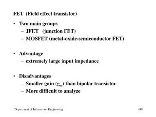
Chapter 12 Field-Effect Transistors 場效電晶體
Chapter 12 Field-Effect Transistors 場效電晶體. Field-Effect Transistors (FETs). FET (場效電晶體) 是利用 電場 來控制 電流的大小 ,而且組成電流的載子僅限 一種 極性,即電洞 或 是自由電子 。 Metal-Oxide-Semiconductor Field-Effect Transistor (MOSFET, 金氧半場效電晶體)可分為 NMOS ( 以 電子 為電流載子 ) 與 PMOS( 以 電洞 為電流載子 ) 。

Chapter 12 Field-Effect Transistors 場效電晶體
E N D
Presentation Transcript
Field-Effect Transistors (FETs) • FET (場效電晶體) 是利用電場來控制電流的大小,而且組成電流的載子僅限一種極性,即電洞或是自由電子 。 • Metal-Oxide-Semiconductor Field-Effect Transistor (MOSFET,金氧半場效電晶體)可分為NMOS (以電子為電流載子)與PMOS(以電洞為電流載子) 。 • MOSFET 包含source (源極)、gate (閘極)、drain(汲極)及body(基座) 。
12.1 NMOS AND PMOS TRANSISTORS NMOS Transistor (n-p-n) 氧化物為絕緣體,沒有電 流能進入閘極端; 控制閘極電壓能夠調整 汲極到源極的電流 (gate 閘極) (drain 汲極) (source 源極) (O, 氧) (M, 金) 場效 (S, 半) (Body 基板)
NMOS (n-channel MOS) • NMOS 之 source (源極)與drain(汲極)為n-type 半導體,body(基座) 為p-type 半導體,gate (閘極)為導體 。 n-p-n
NMOS 的運作 (Operation) • NMOS 的運作可分為三區(region) • Cutoff Region (截止區) • Triode Region (三極區) or Linear Region (線性區) • Saturation Region (飽合區) and and
Operation in the Cutoff Region • 當閘極(gate)與源極(source)間電壓vGS =0,兩個pn接面(body-source) 與(body-drain)可視為兩個方向相反的二極體,此時MOSFET為截止(cutoff)。 • 當閘極(gate)與源極(source)間電壓vGS逐漸上升到>Vto (threshold voltage,臨限電壓)時,則NMOS才會開始導通。
Operation in the Triode Region and • 當閘極(gate)帶正電時,可逐漸吸引自由電子聚集在絕緣層的下方,並將電洞推離絕緣層下方。
Operation in the Triode Region and • 當閘極(gate)與源極(source)間電壓vGS逐漸上升到>Vto (threshold voltage,臨限電壓),且在drain和source之間加有電壓vDS,則形成n-type通道(channel),通道中的自由電子受到外加電場的驅動,形成汲極電流(drain current)iD,其方向從drain流向source,和通道中的電子流方向相反。 • 當vDS很小時,iD與vDS成正比, 亦與vGS- Vto成正比。 • 由於有氧化絕緣層,故閘極電流 iG= 0。
Operation in the Triode Region • In the triode region, the NMOS behaves as a resistor connected between drain and source, but the resistance decreases as vGSincreases. 0,if vDS~0 Device parameter
Operation in the Saturation Region and • 當drain和source之間電壓vDS≥vGS- Vto(or vGD≤Vto) 則n-type通道在drain端寬度變為0 ,vDS再變大, iD不再上升,稱為飽合區。
Boundary between Triode and Saturation Regions At boundary, 使得n-type通道在drain端寬度剛好為0 代入I-V equation in saturation region
Boundary between Triode and Saturation Regions 將 代入I-V equation in triode region 兩者結果一樣。
Example12.1 A NMOS transistor W=160um, L=2um, KP=50uA/V2, and Vto=2 V. Plot the drain characteristic curves to scale for vGS=0, 1,2, 3, 4, and 5 V. 1. 求 K 2. 求 boundary
4. Plot characteristics in the triode region (parabola 拋物線).
PMOS • PMOS 之 source 與drain為p-type 半導體,body為n-type 半導體,gate (閘極)為導體 。 • 以電洞為電流載子。
12.2 LOAD-LINE ANALYSIS OF A SIMPLE NMOS AMPLIFIER • VGG (dc source) 對NMOS 產生偏壓(bias) ,決定操作點, 當ac input 在操作點附近隨時間變化,導致vGS, iD亦隨時間改變。
iD隨時間改變,導致RD亦上的壓降隨時間改變, 使得vDS產生ac output。 KVL Load-line equation Load-line 兩端點
1V VGSQ=4 5V VDQ=11 7V Distortion (變形)
Distortion Distortion is due to that the characteristic curves for the FET are not uniformly spaced. If a much smaller input amplitude was applied we would have amplification without appreciable distortion.
Amplifier Analysis 12.3 Bias Circuits Amplifier analysis has two steps: 1. Determine the Q point. 2. Use a small-signal equivalent circuit to determine impedances and gains.
The Fixed- Plus Self-Bias Circuit 1. Thévenin equivalent
2. KVL 3. Usually, transistor operates in saturation region
Example12.2 Analyze the following circuit. The transistor KP=50uA/V2, Vto=2 V, L=10um, W=400um 1. Determine K 2. Thévenin equivalent
12.4 SMALL-SIGNAL EQUIVALENT CIRCUITS Small signal (ac) Small signal (ac) To determine vgs(t) vs. id(t)
SMALL-SIGNAL EQUIVALENT CIRCUITS At Q point 0