Download
1 / 23
230 likes | 248 Views
Explore the proceedings from the Laser-wire conference at CERN in 2007, detailing advancements in laser wire technology, error correction methods, and plans for future application. Learn about key individuals and their contributions in the field.

E N D
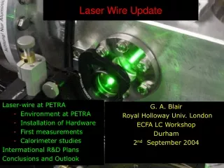
Laser-wireat ATF2 and PETRA Grahame Blair CERN, 18th October 2007 • Introduction • Overview of errors • Ongoing technical work in this area • Plans for the future.
Laser-wire People BESSY: T. Kamps DESY : E. Elsen, H. C. Lewin, F. Poirier, S. Schreiber, K. Wittenburg, K. Balewski JAI@Oxford: B. Foster, N. Delerue, L. Corner, D. Howell, L. Nevay, M. Newman, A. Reichold, R. Senanayake, R. Walczak JAI@RHUL: G. Blair, S. Boogert, G. Boorman, A. Bosco, L. Deacon, P. Karataev, S. Malton , M. Price I. Agapov (now at CERN) KEK: A. Aryshev, H. Hayano, K. Kubo, N. Terunuma, J. Urakawa SLAC: A. Brachmann, J. Frisch, M. Woodley FNAL: M. Ross
Laser-wire Principle • PETRAII • 2d scanning system • DAQ development • Crystal calorimeter • → PETRA III • Ultra-fast scanning • Diagnostic tool
Laser wire : Measurement precision I. Agapov The Goal: Beam Matrix Reconstruction NOTE: Rapid improvement with better σy resolution Reconstructed emittance of one ILC train using 5% error on σy Assumes a 4d diagnostics section With 50% random mismatch of initial optical functions The true emittance is 0.079 m rad
y u x Skew Correction ILC LW Locations Eb = 250 GeV Error on coupling term:
2σL=2cτL Scan of an ILC Train of Bunches αtrainσe 2σe 2αJσe 2σscan Ntrain bunches 2σe (1 + strain) Not to scale!
Need for Intra-Train Scanning For <0.5% effect, strain<0.12; otherwise, the effect must be subtracted For 1m bunches, the error after subtracting for any systematic shift (assumed linear ±αtrainalong the train) is: For <0.5% effect, αtrain<2.6; otherwise, higher precision BPMs required
Machine Contributions to the Errors Bunch Jitter Dispersion BPM resolution of 20 nm may be required Assuming can be measured to 0.1%, then must be kept < ~ 1mm
Alternative Scan Mode • R&D currently investigating ultra-fast scanning (~100 kHz) • using Electro-optic techniques • Alternative: Keep laser beam fixed and use natural beam jitter • plus accurate BPM measurements bunch-by-bunch. • Needs the assumption that bunches are pure-gaussian • For one train, a statistical resolution of order 0.3% may be possible Single-bunch fit errors for BPM resolution fixed at 100 nm Beam jitter fixed at 0.25σ
√2σℓ laser beam xR σey σex σℓ electron bunch Laser Conventions For TM00 laser mode:
Compton Statistics Approximate – should use full overlap integral (as done below…) Where : Compton xsec factor e-bunch occupancy Laser wavelength Laser peak power Detector efficiency (assume Cherenkov system)
TM00 Mode Overlap Integrals Rayleigh Effects obvious • Main Errors: • Statistical error from fit ~ -1/2 • Normalisation error (instantaneous value of ) – assume ~1% for now. • Fluctuations of laser M2 – assume M2 known to ~1% • Laser pointing jitter
TM01 Y. Honda et al TM01 gives some advantage for larger spot-sizes Estat EM2 TM00 TM01 TM01 TM00
Laser Requirements ILC-spec laser is being developed at JAI@Oxford based on fiber amplification. L. Corner et al
ATF2 LW; aiming initially at f2; eventually f1? TM00 mode Statistical Error From 19-point scan • Optimal f-num1-1.5 for = 532nm • Then improve M2 determination • f-2 lens about to be installed at ATF Relative Errors Error resulting from 5% M2 change
Towards a 1 m LW preliminary Resultant errors/10-3 Goals/assumptions Final fit, including dispersion Could be used for measurement → E
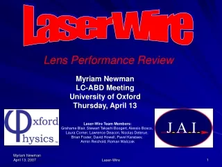
Lens Design + Tests • f-2 lens has been built and is currently under test. • Installation at ATF planned for this year M. Newman, D. Howell et al. Designs for f-1 optics are currently being studied, including: Aspheric doublet Vacuum window N. Delerue et al.
BDS Laser-wire All initial goals have been achieved. New fibre-laser programme at Oxford now under-way in collaboration with EU industry • PETRA – 2d scans, multi-shot. • ATF – micron, single shot • Laser R&D • Fast Scanning R&D • Simulation BDSIM plots. At ATF2: + - Ez - + EO fast scanner under test at RHUL; plan to use at PETRAIII
PETRA LW Routine scans of two-dimensions were achieved PETRAII programme now finished; preparing for PETRAIII Fast scanning system with 130kHz laser at RHUL planned Collaborating with DESY on fast DAQ Look forward to installation in new location for PETRAIII next year 1000 laser shots= 50s. beam: 6 GeV, 0.5 mA. PETRA II
ATF LW Tests of f2 lens system currently underway at Oxford We will improve ATF laser at KEK in October 2007 Look forward to running with f2 optics in Nov 07 and in 2008. quad scan using LW scans single LW scan
ATF2 Laser-wire New LW location New laser hut • Detailed design of layout, • light path, laser hut are underway. • An additional LW location has been reserved downstream for multi-axis scans → LC-ABD-II
ATF/ATF2 Laser-wire • At ATF2, we will aim to measure micron-scale electron spot-sizes with green (532 nm) light. • Two locations identified for first stage (more stages later) • 0.75m upstream of QD18X magnet • 1m downstream of QF19X magnet LW-IP (1) LW-IP (2) σx = 38.92 m σx = 142.77 m σy= 7.74 m σy = 7.94 m Nominal ATF2 optics ATF2 LW-test optics LW-IP (1) LW-IP (2) σx = 20.43 mσx = 20 m σy= 0.9 m σy = 1.14 m P. Karataev Ideal testing ground for ILC BDS Laser-wire system
Summary • Very active + international programme: • Hardware • Optics design • Advanced lasers • Emittance extraction techniques • Data taking + analysis • Simulation • All elements require R&D • Laser pointing • M2 monitoring • Low-f optics • Fast scanning • High precision BPMs • Look forward to LW studies at PETRA and ATF • ATF2 ideally suited to ILC-relevant LW studies. • CLIC Laser-wire parameters will also be studied