Download
1 / 27
270 likes | 288 Views
This paper explores instruction generation techniques for hybrid reconfigurable architectures, focusing on customized macros and computational patterns at the instruction level. The authors propose an algorithm for determining customized functionality transforms and extracting regularity from graphs, which are implemented as customized instructions. The paper also discusses the challenges and trade-offs involved in instruction generation for CAD and embedded system design.

E N D
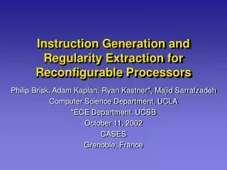
Instruction Generation For Hybrid Reconfigurable Architectures Philip Brisk, Adam Kaplan, Ryan Kastner*, Majid Sarrafzadeh Computer Science Department, UCLA *ECE Department, UCSB October 11, 2002 CASES Grenoble, France
Outline • What is Instruction Generation? • Related Work • Sequential and Parallel Templates • The Algorithm • Experimental Setup • Experimental Results • Conclusion and Future Work
Instruction Generation RAM VPB Set of applications RAM VPB • Given a set of applications, what computations should be customized? Customized (Hard/Soft) Macro in PLD customized? Application Specific Instruction set Processor ALU Register Bank Customized Macros Control • Main Objective: complex, commonly occurring computation patterns • Look for computational patterns at the instruction level • Basic operation is add, multiply, shift, etc.
Customization and Performance • A customized instruction must offer some measurable performance increase. • In this work, we have categorized two types of customized instructions and quantified the performance that they offer us. • Sequential Instructions: • Savings could come from either instruction fetch reduction or datapath optimization. (e.g. ADD-ADD converted to 3-input ADDER) • Parallel Instructions: • Given multiple ALUs and data paths, allow data independent instructions to be computed simultaneously.
Problem Definition • Determining customized functionality transforms to regularity extraction • Regularity Extraction - find common sub-structures (templates) in one or a collection of graphs • Each application can be specified by collection of graphs (CDFGs) • Templates are implemented as customized instructions • Related problem: Instruction Selection
What Is Instruction Generation? MOV MEM MEM + + MEM * FP X + Ti 4 FP a The Instruction Selection Problem R1 M[fp + a] R2 Ti + 4 R1 R1 + R2 R2 FP + X M[R1] M[R2] Templates given as inputs. How do we determine templates?
What Is Instruction Generation? The Alternative : Instruction Generation • Reconfigurable architectures allow us to rethink the assumptions underlying our notion of instruction selection. • The target machine language can be changed by reconfiguring the FPGA to implement new instructions. • This presents new challenges for mapping IR to machine language. • We propose a scheme by which this mapping could be obtained at compile time.
What Is Instruction Generation? Instruction Generation : Applications to CAD and Embedded System Design • Template Generation plays a role in the interaction between compilation and high-level synthesis. • Each template corresponds to a resource which must be provided by the underlying architecture. • A high-level synthesis tool can then allocate resources and schedule the operations on these resources. • This work investigates the latency-area tradeoff created by instruction generation.
Related Work • Similar techniques have proven beneficial in reducing area and increasing performance for the PipeRench Architecture (Goldstein et al. 2000) • Corazao et. Al have shown that well matched, regular templates can have a significant positive impact on critical path delay and clock speed • Kastner et al. (ICCAD02) formulated an algorithm for template matching as well as template generation for hybrid reconfigurable systems
if (cond1) bb1(); else bb2(); bb3(); switch (test1) { case c1: bb4(); break; case c2: bb5(); break; case c3: bb6(); break; } bb7() Our Model of Computation:Control Data Flow Graphs T cond1 bb1() F bb2() bb3() c3 test1 c1 c2 bb4() bb5() bb6() bb7() bb – basic block
Instruction Generation • Ideally, we want large templates that occur often. • The basic idea: an iterative process whereby we examine dataflow graphs and cluster combinations of nodes that occur frequently. • Sequential Template Generation – Identifies templates where the IR operations have data dependencies between them. • Parallel Template Generation – Identifies dataflow operations that may be scheduled in parallel.
Sequential Template Generation • Algorithm designed Kastner et al. [ICCAD 2001]. • Basic idea is to examine each edge in the DFG. The type of edge can be represented by an ordered pair consisting of the starting and ending node types. • Maintain a count for each edge type. • Cluster the most frequently occurring edge by replacing both vertices (head and tail) with a super-vertex maintaining the original vertices in an internal DAG.
Sequential Template Generation VAR IMM VAR LDA NEG VAR IMM MUL MUL MUL MUL ADD ADD MUL VAR MUL VAR ADD ADD LOD
Parallel Template Generation • Instead of examining DFG edges, we must determine whether pairs of computations can be scheduled in parallel. • We introduce a data structure called the All-Pairs Common Slack Graph (APCSG) to help us with this analysis. • APCSG edges are placed between nodes that could possibly be scheduled together. • Two nodes can be scheduled at the same time if they share common slack between them.
All Pairs Common Slack Graph (APCSG) • Common Slack – the total number time steps that two operations x and y could be scheduled using by some scheduling heuristic. • APCSG – undirected graph • Nodes correspond to operations • Edges represent the common slack between every operation
All-Pairs Common Slack Graph (Example) 1 A B C A 1 B 2 C 1 1 D E 1 D 1 E 1 F F G G
Parallel Template Generation Algorithm 1. Given: A Labeled Digraph G(V,E) 2. # T is a set of template types 3. T {} 4. while not stop_conditions_met(G) I. APCSG create_apcsg(G) II. T determine_template_candidates(APCSG) III. cluster_vertices(G,T)
Parallel Template Generation VAR VAR IMM IMM VAR LDA MUL MUL MUL MUL MUL ADD ADD MUL VAR VAR MUL ADD ADD LOD
Stopping Conditions • So… when should we stop clustering a graph? • Aside from pragmatic arguments, a correct stopping condition is essential if we are to prove that our template generation algorithm is optimal based on some criteria.
Stopping Criteria We Have Considered Stopping Criteria We Have Used • Percentage of Nodes covered • Number of nodes left in the graph • Ratio of the number of nodes in a graph before and after clustering • Number of unique template types exceed a given threshold • Templates Exceed a Given Size • Percentage of overall slack lost in the graph over an iteration. • Template sizes are restricted to be <= 5 nodes total. • The algorithm stops when the total number of nodes is less than half of what was started with...
Scheduling Constraints You MUST do these operations together… + + + + * SCHEDULER + ALU1 CLK × 1 2 … Essentially, we have scheduled our operations at the compiler level. What kind of job did we do?
Measuring The “Damage” SCHEDULER + ALU1 CLK × LENGTH OF SCHEDULE 1 2 … • Length Of Schedule • The latency of all the operations… • Ideally we want it short. • We must measure resulting clustered DAGs • Original, non-clustered DAG • Sequential Templates Only • Sequential and Parallel Templates
Experimental Setup COMPILER IR (SUIF) Sequential Template Generation Algorithm Data Flow Graph and DAG Generation from a CDFG pass CO - COMPILER A High Level Synthesis Tool Using A Locally-Optimal Geometric Scheduling Algorithm
Benchmarks • CONVOLUTION: Image convolution algorithm. • DeCSS: Algorithm for breaking DVD encryption • DES: The cryptographic symmetric encryption standard for over 20 years. • Rijndael AES: The new advanced encryption standard.
Experimental Procedure • First, we compiled the program to the SUIF IR using the front end built by The Portland Group and Stanford University. • Next, we converted the SUIF IR to CDFG form • Then, we performed template generation on each basic block for each program. • We selected 4 large dataflow graphs from each program to schedule and evaluate our result. • We scheduled the dataflow graphs following template generation and and compared them to the original graphs.
Conclusion And Future Work • The sequential template generation algorithm can be expanded to accommodate parallel templates. • Parallel template generation reduces latency at the expense of slack and area. • In the future, we plan to repeat these experiments • with a more realistic architecture description • with ability to cross-schedule parallel instructions • We also plan to explore compiler transformations, such as function inlining, to: • extract even more regularity • determine a more global view of the program