Download
1 / 1
10 likes | 159 Views
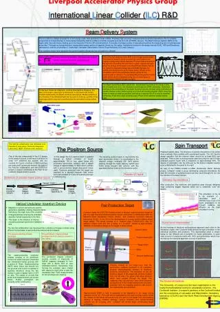
The Liverpool Accelerator Physics Group is at the forefront of developing advanced simulations and technologies for studying polarised electron and positron beams. Utilizing helical undulators and innovative targets, such as the water-cooled titanium disc, we aim to enhance beam polarisation to improve particle interactions. Our work, part of the PPARC-funded LC-ABD project and the EUROTeV collaboration, underscores the importance of spin-polarised beams in precision physics, with the ILC design specifying polarisation levels for enhanced accuracy.

E N D
Liverpool Accelerator Physics Group TESLA parameters Photons(≈ 10 MeV ) PINIT=1.0 Helical Undulator (≈ 200 m) Electrons (150 GeV to 250 GeV) Polarised Positrons (≈ 5 MeV) Conversion Target (0.4X0 Ti) Photon Collimator low Q parameters PINIT=1.0 Spin Transport Polarised beams allow the structure of particle interactions to be probed more precisely than possible with unpolarised beams. The ILC baseline design specifies that the electron beam should be at least 80% spin-polarised. There is also a strong physics case favouring the use of a spin-polarised positron beam with a polaristion of approximately 60%. This degree of polarisation can be achieved by the helical undulator positron source described in the panel to the right. As part of the PPARC-funded LC-ABD (Accelerator Beam Delivery) project, Liverpool heads a group developing computer simulations that track the evolution of polarised beams as they travel through the ILC from the sources to the beam dumps. Damping ring simulations After production, the electrons and positrons pass through damping rings containing wiggler magnets which act to radiatively ‘cool’ the beams. The simulation to the left is an example of a calculation used to estimate how much of the beam polarisation is lost through radiative spin diffusion as the beam circulates in a ring. Helical Undulator Insertion Device Pair-Production Target • Magnets or current elements are used to generate a (spatially) rotating magnetic dipole field along the major axis of the undulator. • Charged particles entering the undulator describe helical trajectories in the field. • This leads to the emission of intense circularly-polarised synchrotron radiation on axis. Liverpool heads the EUROTeV-funded project to develop a pair-production target as part of a high-intensity polarised positron source, and works in collaboration with the Stanford Linear Accelerator Centre (SLAC) and Lawrence Livermore National Laboratory (LLNL) in the US on the development of a water-cooled rotating wheel target design. The wheel consists of a titanium alloy (Ti-6%Al-4%V) disc 0.4 radiation lengths thick and with a radius of 1 m which rotates at approximately 1000rpm. A conceptual design for the target is shown below. Bunch-bunch depolarisation As the bunches of electrons and positrons approach each other in the interaction region, their Coulomb fields perturb the spin orientation of the individual electrons and positrons. This depolarising effect is shown below for two different set of possible ILC beam parameters. In each case a bunch of electrons starts with 100% spin-polarisation which then evolves as the electrons approach a bunch of positrons. The heLiCal collaboration has developed two undulator prototype modules using different technologies: superconducting and permanent magnet. Capture Optics The superconducting module prototype. The permanent magnet module prototype (built at Liverpool) shown in two halves. Positron beam pipe Target wheel Photon beam pipe Spread in Polarisation Motor Before Interaction During Interaction After Interaction The superconducting undulator module consists of an aluminium former into which has been machined two interleaved helical grooves with a period of 14mm. Superconducting (NbTi) wires ribbon are wound into the grooves and current is passed in opposite directions along the two helices to give a design field of 0.8T on axis. The results of on-axis Hall probe field measurements are shown below. Further prototypes are currently under construction. Vacuum feedthrough The permanent magnet undulator module consists of trapezoids of NdFeB magnets arranged to form rings with a dipole field on axis (illustrated below). Successive rings forming the undulator were rotated with respect to each other to give the necessary field. Field measurements for this prototype are ongoing. Photons incident on the target (e.g. from the synchrotron radiation produced in an undulator) produce electromagnetic showers of electrons, positrons and photons. The simulation on the left shows a square of the target with photons incident from the left side. The green lines show photons which have passed through the target. The (relatively few) red and blue lines show electrons and positrons. If the incident photons are circularly-polarised then the outgoing positrons will tend to be longitudinally spin-polarised. Before Interaction During Interaction After Interaction The Cockcroft Institute The University of Liverpool is the lead organisation in the newly formed national centre for accelerator science - the Cockcroft Institute. Liverpool’s partners in the Cockroft Institute are the universities of Lancaster and Manchester, Daresbury laboratory (CCLRC) and the North West Development Agency (NWDA). Approximately 20kW of heat is expected to be deposited in the target during operation at the ILC. The heat will be dissipated by the water-cooling system whilst the rotation of the wheel will prevent any one spot on the target from over-heating. Studies of heating, radiation damage, neutron activation and remote-handling systems are all on-going, and Liverpool will shortly begin constructing target prototypes. International Linear Collider (ILC) R&D Beam Delivery System The ILC (left) is a design proposal for a TeV energy-scale ‘next generation’ linear collider. Providing high-accuracy measurements of particle interactions, the ILC physics programme is complementary to those being followed by hadron colliders of similar energies such as the LHC at CERN, Geneva. The Beam Delivery System (BDS) is the region after the main linacs, leading up to the Interaction Point(s) (IP) and detector(s). It consists of a large number of specialised sections for measuring and correcting beam properties. The beam is transported and manipulated using a series of magnets, known as the optics. Institutions involved in the design include SLAC, KEK and Daresbury laboratories, and the universities of Cambridge, Lancaster, Manchester, Oxford, Royal Holloway, UCL and Liverpool. The numbers shown here represent the current baseline design and are all subject to change! Layout of the BDS (below left and below right) . The beam size is given by where e and p are the beam emittances and momenta, and D is the dispersion of the beam. One of the first sections of the BDS is an energy spectrometer. The beam is forced to bend out and then return back to its original course using dipole magnets. Precise measurements of the amount of bending that occurs for a given magnet strength allow the energy of the beam to be determined. Beams that do not have the expected energy can potentially damage the collider and must be sent to the beam dump. Shown to the immediate right is the preliminary design optics for the spectrometer or chicane. The bending affects the position of the beam which can be measured using one of many types of Beam Position Monitor (shown far right). Possible ILC layout. The Beam SwitchYard (BSY, below left) sends beam bunches to the dump if they are unusable and on to the interaction points/regions (IP/IR) otherwise. Unwanted particles in the extremities of the beam bunches can be removed using collimators or spoilers (below center) before going on to the final focusing doublet (right). Here the beam is made as small as possible just before it reaches the IP to ensure maximal luminosity. A low and a high crossing angle IP are in the baseline design (below right). A new tool, known as Laserwire, is being developed to measure the size of the beam. Laser light is directed on to the beam and is then forward scattered by the beam bunches (see below). Measurements of the intensity of the deflected light can be used to build up a profile of the beam spot which may look something like the simulation shown below left. The heLiCal collaboration has members from Daresbury Laboratory, Rutherford Appleton Laboratory, DESY, Durham and Liverpool. The Positron Source One of the key components of the ILC design is the positron source. It will have to produce of order 1014 positrons per second, with the nominal ILC bunch structure of 2820 bunches per pulse and 5 pulses per second. As a part of the heLiCal collaboration and the EUROTeV project, Liverpool contributes to the R&D for an undulator-based positron source. In this design the ILC electron beam is passed through a helical undulator of length approximately 100 m (see panel below left) producing synchrotron radiation with a typical energy of approximately 10 MeV which collides with a pair-production target (see panel below right). Positrons produced from the target are captured by a tapered magnetic field before being accelerated to 5 GeV and passing through a damping ring. The resulting positron beam is injected into the main accelerator where it is accelerated to the required energy (nominally 250 GeV) before passing through the beam delivery system and finally being brought into collision with the opposing electron beam at the interaction point. Possible ILC layout. Schematic of undulator-based positron source.