Download
1 / 41
420 likes | 449 Views
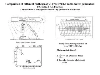
In this study by Nikolai G. Lehtinen, March 2008, the HF heating of the ionosphere and ELF/VLF radiation generation are explored through a time-dependent solution that considers various physical processes.

E N D
Theoretical modeling of HF heating and ELF/VLF wave generation Nikolai G. Lehtinen March 2008
Time-dependent solution for - almost isotropic, time dependence is slow compared to w Relevant physical processes inluded in ELENDIF: Elastic scattering on neutrals and ions Inelastic and superelastic scattering Electron-electron collisions Attachment and ionization New: Non-static (harmonic) electric field (was: quasistatic) Geomagnetic field Kinetic equation for electron distribution f(v) due to HF heating
Dynamic friction force -effective force experienced by electrons moving through atmosphere N2 vib. barrier Inelastic processes: • Rotational • Vibrational • Electronic level excitations • Dissociative losses • Ionization (E/N)br=130 Td where 1 Td = 10-21 V-m2
Results for f(v) Electron distributions for various E/Ebr Extaordinary wave HF heating at h=90 km • Effective electric field is smaller than in DC case: + o-mode ordinary (CW in B0 direction) - x-mode extraordinary (CCW) Extaordinary mode is more effective for heating as it resonates with gyrating electrons
Self-consistent HF wave propagation • Power flux S attenuates due to losses from HF conductivity sHF • HF conductivity sHF is a function of electron distribution f(v) • Electron distribution f(v) is calculated from Boltzmann equation, with the driving E field of the HF wave obtained from S
Electric field at HAARP, steady heating (f=3.1MHz, x-mode) • Electric field decreases with time due to self-absorption no absorpsion
Effective temperature • Current HAARP power is high enough for the changes to be both nonlinear and non-Maxwellian (results for f=3.1MHz, x-mode) current power level Linear (DT ~ E2)
Steady heating • N2 vibrational barrier is not exceeded by upgraded HAARP
Electrojet current modulation • The electrojet current is modulated: DJ=DsE0 where the conductivity is a tensor with components which are called Pedersen (sp) Hall (sh) and parallel (sz) • Conductivity is modified due to changes in the electron distribution f(v) (i.e., heating)
Square-modulated heating • Absolute change and harmonic contents of conductivity depends on non-thermal effects at current HAARP power level
Square-modulated heating (2) • The effect is higher if the power is increased
Future work • Long time scale heating effects • Generalization to 3D: Non-vertical HF wave propagation
Long-time-scale heating effects • Ionosphere chemistry model [Lehtinen and Inan, 2007]: • 5 species • Dynamics on t > or ~1 s scale • The red coefficients depend on electron distribution f(v)
Non-vertical propagation and ray divergence • Ray tracing for HF propagation Effect on HF heating: beam spreading
VLF/ELF emission and propagation • We use a new full-wave method (FWM) to calculate fields radiated by the modulated electrojet current • FWM Capabilities: • Arbitrary plane stratified medium, e.g., a horizontally-stratified magnetized plasma with an arbitrary direction of geomagnetic field (ionosphere) • Arbitrary configuration of harmonically varying currents • Provides full wave 3D solution of both whistler waves launched into ionosphere and VLF waves launched into Earth-ionosphere waveguide • Stable against the “swamping” instability by evanescent waves • Efficient use of the computer resources
Method description • We work in Fourier (wave vector k) domain • k^ = const (Snell’s law) find kz, E and H in each layer • Use continuity of E^ and H^ between layers to find reflection coefficients and mode amplitudes • Represent source currents as boundary conditions on E^ and H^ between layers • Inverse Fourier transform from k^ to r^
Finding the modes in each layer • Solve uniform Maxwell’s equations for plane waves (~e-iwt+ikr) • The fields are a combination of 4 different solutions, corresponding to different nz
Waves in magnetized plasma • Solid = Re(nz) • Dashed = Im(nz) • In VLF/ELF frequency range, the 4 solutions are upward and downward whistler and evanescent waves
Waves in a highly-collisional medium • Solid = Re(nz) • Dashed = Im(nz) • Z >> X • The modes are (almost) like in vacuum, with |n|=1
Emission of ELF waves by HF-heated modulated electrojet • Modulation frequency=1875 Hz • Change in electrojet current is caused by HF heating • The current has a horizontal pancake shape
Collimated whistler beam and wave in Earth-ionosphere waveguide
Simulation of a satellite pass • non-zero displacement (target parameter) from the maximum of the emission
Field on the ground • The observed field on the ground is due to both near field and propagating Earth-ionosphere waveguide modes.
Main results of the study of theELF generation by HF heating • ELF emission by the HF-heated spot creates a collimated upward whistler beam • Calculated emitted energy is ~3 W into magnetosphere, ~1 W into Earth-ionosphere waveguide, for fmod=1875 Hz
Efficiency of emission as a function of modulation frequency • Because of the resonance in the Earth-ionosphere waveguide, some frequencies are more efficient
Understanding the energy flow from the electrojet “antenna” • The Earth-ionosphere waveguide mode “leaks” into ionosphere
Other uses of FWM • Ground-based transmitter radiation • Signals generated by a current pulse in time domain • Whistler penetration from ionosphere into the Earth-ionosphere waveguide
Ground-based transmitter radiation • The fields radiated by a VLF transmitter can be calculated both at the satellite and on the ground • VLF waves incident on ionosphere become whistlers
Radiation from NWC(Australia) • F=19.8 kHz, P0=1 MW, ~180 kW transmitted through ionosphere • The energy goes from the main wave packet (vg is between B0 and vertical) into the electrostatic waves which are mapped along B0
Whistlers and Lower Hybrid (Electrostatic) waves • Whistlers are circularly polarized waves with H~nE, but at high values of k^ (in respect to B) they become electrostatic waves (i.e. E || k, H is small) • k^ becomes infinite at the resonance cone • When ions are included, the whistler refractive index surface may close at high values of k^ (with k||=0), i.e. the resonance cone disappears • The resonance occurs at k ^B at the lower hybrid frequency (the lower hybrid resonance)
Application of FWM to time domain:Radiation from a current pulse • Calculate field for many different frequencies • Apply an inverse Fourier transform: w t • Use the spectrum of a given current pulse (e.g., lightning discharge) to calculate field in time domain
The signal on the ground (movie) There are multiple pulses due to reflection from ionosphere
The signal at 120 km (movie) High frequencies arrive before low, which is a characteristic dispersion of a lightning-generated whistler
Wave packet parallel to geomagnetic field Whistler propagating along the geomagnetic field
Future work on FWM • Current work: Non-stratified medium, by the way of horizontal segmentation (an example follows) • Include Earth curvature • Scattering on irregularities (whistler - LH wave conversion) - requires non-conservation of k^
Horizontal segmentation We can represent the incoming wave as a vertical sheet between Region 1 and Region 2 with fictitious surface electric and magnetic currents:
The emission from the fictitious “currents” is forward • Blue - original • Green - the “re-emitted” wave
Summary • We developed a fully kinetic model of self-consistent HF wave heating of the D region and found the changes of conductivity • We applied the new full-wave method to find the electric and magnetic field radiated by modulated electrojet current • The new full-wave method has a multitude of applications for wave propagation in the Earth-ionosphere system