Download
1 / 1
10 likes | 136 Views
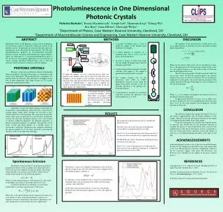
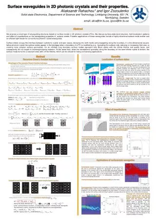
V. V. perturbation (hopping) operator. V. +. +. n. m. Transmission Velocity / c. Smaller rods Larger rods, mode I Larger rods, mode II. Directional diagram. Surface waveguides in 2D photonic crystals and their properties.

E N D
V V perturbation (hopping) operator V + + n m Transmission Velocity / c Smaller rods Larger rods, mode I Larger rods, mode II Directional diagram Surface waveguides in 2D photonic crystals and their properties. Aliaksandr Rahachou* and Igor Zozoulenko Solid-state Electronics, Department of Science and Technology, Linköping University, 601 74, Norrköping, Sweden email: alira@itn.liu.se, igozo@itn.liu.se Abstract We propose a novel type of waveguiding structures based on surface modes in 2D photonic crystals (PCs). We discuss surface-state band structure, field localization patterns and effect of imperfections on the waveguiding properties of surface modes. Possible applications of these waveguides include a highly-directional surface-mode emitter and an efficient light feeder for conventional photonic crystal waveguides. Surface states occupy the interface between a photonic crystal and open space, decaying into both media and propagating along the boundary. In a two-dimensional square-lattice photonic crystal the surface states appear in the bandgap when a boundary of a PC is modified by e.g., truncating the surface rods, reducing or increasing their size, or creating more complex surface geometries. On an infinitely long boundary surface modes represent truly Bloch states with the infinite lifetime and quality factor, and consequently do not couple to incoming/outgoing radiation. At the same time, when the translational symmetry along the boundary of the semi-infinite crystal is broken, the surface mode turns into a resonant state with a finite lifetime, which can be utilized for lasing and sensing applications Results Method Recursive Green’s function technique Localization of surface states • Advantages of the recursive Green’s function technique: • accounts for an infinite extension of the photonic structure (the scattering states are Bloch states of the periodic infinite structure) • computes the photonic structure recursively by adding slice by slice, which eliminates the need for storing large matrices and facilitates the computational speed • unconditionally stable Structure (a) – smaller rods: At low energies a significant part of the field intensity extends into a wide air layer near the surface of the PC. This can be attributed to the proximity between the dispersion curve of the surface state and the light line, where the group velocity of the surface state is close to the speed of light, c. At higher energies, the dispersion curve moves away from the light line, and the field becomes mainly concentrated on the surface rods. Structure (b) – larger rods: The field is located within each cylinder and has a node oriented either horizontally (mode I) or vertically (mode II). In contrast to case (a) the intensity of both surface modes is mainly localized within the surface rods and its extent to the air is small for the whole energy range. Maxwell’s equations(TM modes): Discretizing the differential operator Lwe arrive to the finite difference equation We construct two test photonic crystals entirely consisting of corresponding surface rods The shape of the surface state (a) closely follows the valence band of the test crystal in the GX-direction. The same situation holds also for structure (b), where both surface bands mimic the bulk levels in the conduction band of the corresponding test PC. A convenient way to solve a finite-difference equation on a grid is to introduce a corresponding tight-binding operator describes an empty lattice describes an excitation at the site m,n Introduce the creation and annihilation operators, amn+ and amn according to the rules Effect of imperfections The system is now divided into three regions: left and right semi-infinite periodic structures (perfect waveguides for surface modes), and the block of the PC (5 unit cells width) in between as an imperfect region. Bloch modes propagate in perfect waveguides from the infinity into the imperfect region where they undergo scattering. The discretization of the circular rods of PCs using a square grid lattice leads to deviations from an ideal circular geometry, which can be treated as roughness of the structure. The discretization of the rods in the periodic waveguides is deliberately chosen differently from that for the central region! Meaning of terms: n n n n m m m m Introduce Green’s functionG(ω): with help of Green’s function one can calculatesystem responseto the incoming state i The transmission coefficients for each surface mode drop quite rapidly in the energy regions corresponding to the low velocity of the surface state. This is because the backscattering probability is greatly enhanced for the low-speed states. Slow states for structure with enlarged surface rods are the most strongly affected. Even for 5 imperfect unit cells the transmission coefficients for both modes approaches 1 only in very narrow energy range, which makes these states hardly appropriate for waveguiding purposes. At the same time the transmission coefficient for the fast surface state in the structure (a) with the smaller boundary rods remains 1 in a wide energy region which makes it better candidate for waveguiding applications. divide the system into semi-infinite ”waveguides” and an internal region + + Calculate the Green’s functions of an internal region using the Dyson’s equation Applications of surface-state waveguides Surface-state coupler: Composed of a surface-state waveguide (to the left) and a conventional tapered PC waveguide (to the right). The diameter of the surface rods in the surface-state waveguide gradually decreases to zero in the region of the conventional PC waveguide. In this device an incoming state in the surface-mode waveguide region enters a tapered region where it is adiabatically transformed into conventional waveguiding state. The maximum achieved transmission reaches 80% (see the inset). Calculate the total Green’s function G of the entire system using the Dyson’s equation Directional emitter: Surface mode propagates in a semi-infinite surface waveguide corresponding to the structure (a) with smaller surface rods. The most of the beam intensity is localized within a range 20o. Inset shows the transmission coefficient T for the surface state propagating into open space. T is close to unity in the energy region corresponding to high velocity of the surface state and drops rapidly for energies where the velocity of the surface state decreases. The origin of a rather narrow beaming cone is related to the fact that the surface state occupies a wide spatial region near the surface~10a (as opposed to conventional waveguides whose width is typically ~a). The angular spread in this case due to the diffraction, sinQ~l/10a is consistent with the calculated far-field radial distribution of the Poynting vector. At higher energies of the incoming light increases, the surface mode becomes more localized, and the spread of the outgoing radiation increases. Using Green’s function, one can calculate transmission amplitudes