TRACI-XL Demonstrator under Development
190 likes | 373 Views
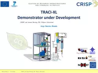
TRACI-XL Demonstrator under Development. CRISP: 2nd Annual Meeting, PSI, Villigen, Switzerland. Jorge S á nchez Rosado. Work package 13 – CO 2 Cooling CRISP : 2nd Annual Meeting, PSI, Villigen, Switzerland. TABLE OF CONTENTS STS-CBM thermodynamical requirements

TRACI-XL Demonstrator under Development
E N D
Presentation Transcript
TRACI-XL DemonstratorunderDevelopment CRISP: 2nd Annual Meeting, PSI, Villigen, Switzerland Jorge Sánchez Rosado Work package 13 – CO2 Cooling CRISP: 2nd Annual Meeting, PSI, Villigen, Switzerland
TABLE OF CONTENTS • STS-CBM thermodynamical requirements • I-2PACL principle (Under patent) • Introduction to TRACI-XL • System diagram (State points + Ph diagram) • CO2 Line • Remote head pump • Pulsation Dampener • Accumulator • Condensing Unit + Interface (Heat exchanger) • P&ID • Control system Work Package 13 - CO2 Cooling - Jorge Sánchez
STS-CBM thermodynamical requirements • The requirements for the STS cooling are twofold: • The innermost sensors with high radiation load have to be kept at or below -5 ⁰C • Cooling based in gaseous, convective cooling of the (innermost) silicon sensors and other heat generating components, like power cables. • Complete removal of the heat dissipated by the front-end electronics boards. This a prerequisite of the first requirement. • System based in an evaporative CO2 cooling of the front-end electronics, which is located in the FEE blocks. • This kind of evaporative cooling based on CO2, is also under consideration and thus under intense technical development for upgrades of the silicon trackers of LHC experiments. The total heat power dissipated by the STS components is estimated as: 212 FEE blocks at 200 W (10 FEBs with 20 W each), resulting in a power dissipation of 42.4 kW. The innermost sensors around the beam pipe with the highest radiation load will dissipate in operation around 6 mW on (2 x 3) cm2 after the accumulation of a certain radiation dose. Work Package 13 - CO2 Cooling - Jorge Sánchez
2. I-2PACL principle (Under patent) Work Package 13 - CO2 Cooling - Jorge Sánchez
3. Introduction to TRACI-XL P = 1kW @ -30 ⁰C Liquid piping: O.D. 1/4 “ = 6.35 mm th= 0.889 Liquid+gaspiping: O.D. 3/8 “ = 9.525 mm th= 0.889 2000 1000 • Upgrade of TRACI up to 1kW unit. • Accumulator MARCO’s Adaption • LEWA remote head Pump • PLC Siemens Simatic S1200 controlled Work Package 13 - CO2 Cooling - Jorge Sánchez
CO2 Line 4. System diagram (State points + Ph diagram) FL 3 VL ø3/8”x0.035 Gas line ø1/4”x0.035 Liquid line 2 Fill Thermal Box FT FL Concentric Hose 5 6 1 kW VL Flow regulation VL VL Q VL Accumulator Control Accumulator PM 7 4 Ac Control Box 1 Experiment venting HT Set Point VL Condensing Unit PR 8 1 Heat Exchanger 2 5 Capacity Control Compressor TEV 3 4 R404a Condenser TRACI-XL Work Package 13 - CO2 Cooling - Jorge Sánchez Vessel
4. System diagram (State points + Ph diagram) -45 ⁰C -40 ⁰C -30 ⁰C Work Package 13 - CO2 Cooling - Jorge Sánchez
1-2 Pumping: Psuctionline = 15 bar Pdischargeline = 27 bar ΔPpump = 12 bar h1(-45) = 102.57 kJ/kg Qpump?? = mco2(h2-h1) = = 0.015(108.88-102.57) = 0.09 kW increment of 3 ⁰C h1 = 102.57 kJ/kg h2 = 108.88 kJ/kg 2-3 Coil heating: Qcoil = mco2 (h3 – h2) =0.165 kW h3= 119.88 kJ/kg 3-4 Inner hose: Qtransferline= mco2 (h4 – h3) = 0.3 kW h4= 139.88kJ/kg (Hose calculation required) 4-5 Restriction valve: ΔP = -12 bar h5 = h4 = 139.88 kJ/kg 5-6 DETECTOR: Qdetector = mco2 (h6 – h5) = 1kW h6= 206.55 kJ/kg 6-7 Outer hose: Qtransferline = mco2 (h7 – h6) = 0.3 kW h7=186.55 kJ/kg (Hose calculation required) 7-1 Heat Exchanger: Qhex= mco2 (h1 – h7) = -1.26 kW interpolating we should set up the compressor working at: 30 hz provides 0.5kW 87 hz provides 1.6 kW Therefore 1.26kW are providing fixing a frequency of 69.38hz Work Package 13 - CO2 Cooling - Jorge Sánchez
5a. CO2 Line: Remote Head Pump oil transfer line redesigned @ GSI AeroShell Fluid 4 At least 30° inclination & Less than 1m QTRACIXL = 48.30 l/h Work Package 13 - CO2 Cooling - Jorge Sánchez
5b. CO2 Line: Pulsation Dampener Necessity of a pulsation dampener to prevent pulsations which produce negative effects in the stability of the temperatures and therefore in the heat extraction by the biphasic system. Dampener effect • Discharge pressures LEWA pump: • Pd,min=22 bar Pd,max=79 bar • Pmin=P1=20.9 bar Pmax=P2=82.95 bar • Dampener should be able to work in this range. • Pt ≈ theoretical or work pressure. Residual pressure admitted ±5% (by now) • P1 = Pt1 - ( 5/100 ) ∙ Pt2 = 20.9 bar (1) • P2 = Pt2 + ( 5/100 ) ∙ Pt1 = 82.95 bar • Plunger: ø=25mm L=15 mm dv=7363.11 mm3 • If V1 = V0 – v, and v = 0.1 ∙ V0 • We have V1 = 0.9 ∙ V0 (2) • And also V2 =V1- dv (3) • From (1) and (2) we obtain P0=0.9xP1 = 18.81 bar (4) • Finally from (1) (2) (3) and (4) we will obtain: • P0 ∙ V0=P2 ∙ V2 ; 0.9P1 ∙ V0=P2 (V1-dv) =P2 (0.9V0-dv) • From the underlined equalities we have the final formula • This will change the charging gas value at 20 ⁰C (take note that for a 10 ⁰C of temperature variation the gas pressure will change approx. a 3%) • This volume has to be equal to ”V2” from the formula P2/P0 = V0/V2 then: • ( V0 / 13.67 ) = ( 82.95/ 18.81 ) and V0 = 60.28 cm3 • Values for a possible version applied in TRACI-XL: • Bladder: NBR Low Temperature -40/85 ⁰C • With 150 ml of oil for low temperatures inside the bladder • Pre-charged at 18 bar Work Package 13 - CO2 Cooling - Jorge Sánchez
5c. CO2 Line: Accumulator Data sheet: 1x Accumulator, according to drawing 1-10.456-01 Design code : R.T.o.D. / PED Design conditions : 110 Barg @ -55/40°C (vessel). Design conditions : 110 Barg @ -55/40°C (coil). Medium : Harmless, gas. Category / Module : II / A1. Material : 1.4404/316L. Corrosion allowance : 0mm. Shell : ø168.3x10.97mm, LG.400mm. Heads : 2x pipecap, 6”sch.80s. Coil : ø6.35x1.24mm. Connections : See drawing. resizing - Resizing of the diameter of the coilto ¼” - Inlet and outlet coming from the top of the vessel instead like from the bottom as in MARCO Work Package 13 - CO2 Cooling - Jorge Sánchez
6. Condensing Unit +Interface (Heat exchanger) System performance: at 30 Hz aprox. ; Qo = 0,50 kW, To = -45 ⁰C, Tsuction = -30 ⁰C, Tc= +35 ⁰C, Tsc = 3 K, Tsh = 5 K? R404a. at 87 Hz aprox. ; Qo = 1,60 kW, To = -45 ⁰C, Tsuction = -30 ⁰C, Tc = +35 ⁰C, Tsc = 3 K, Tsh = 5 K? R404a. All parts functionally mounted on the compressor base plate. - Compressor with crankcase heater, discharge and suction service valve, frequency inverter, HP/LP safety switch. - Discharge line with vibration damper. - Condenser with condenser fan 1x230V. - Hot gas bypass valve including service valve. - Alfa Laval heat exchanger AXP10-10H-F - Swagelok connections on CO2side. - Suction line mounted with vibration dampener and suction accumulator both insulated with Armaflex. - Gauge panel with two service valve, LP and HP pressure transmitter. Recent provider change Work Package 13 - CO2 Cooling - Jorge Sánchez
6. Condensing Unit +Interface (Heat exchanger) • Reliable brazed heat exchanger used @CERN with enough capacity for a maximum 1.6 kW provided by the chiller. • In terms of pressure is more than enough for CO2 applications. Work Package 13 - CO2 Cooling - Jorge Sánchez
7. P&ID Based in EN81346-1, EN81346-2, EN 61175 will be translated to CERN nomenclature Work Package 13 - CO2 Cooling - Jorge Sánchez
7. TRACI-XL Control System • For TRACI-XL PLC Siemens S1200 replaces rail transmitters used in TRACI • Distributed Inputs/Outputs modules • PROFINET protocol • HMI touch panel to have total automation control from TRACI-XL Data logging 800 544 In contact with Siemens to clarify 847 Siemens TIA V11 (2 licenses @ CBM) Control cabinet 544x800x847 enough? PROFINET protocol Work Package 13 - CO2 Cooling - Jorge Sánchez
Analog inputs • RTD signal (Pt 100) • (1) BT01 (Temperature transmitter - pump inlet/heat exchanger output) • (2) BT02 (Temperature transmitter - pomp outlet) • (3) BT03 (Temperature transmitter – Accumulator gas) • (4) BT04(Temperature transmitter – Accumulator coil outlet) • (5) BT05(Temperature transmitter – supply line,before lexible trans. line) • (6) BT06(Temperature transmitter – experiment input) • (7) BT07 (Temperature transmitter – experiment output) • (8) BT08 (Temperature transmitter – Heat exchanger input) • Other sensors • (1) BT09(Termocouple type K on EB01) • (2) Experiment heater protection • (3) BP01(Pressure transmitter – accumulator pressure) • (4) BP02(Pressure transmitter - supply line,before flexible trans. line) • (5) Pressuretransmitter – R404A chiller suction line • (6) BF01(Mass flow meter) • Digital output • Compressor frequency, • Chiller condenser fan • Service valve(HB chiller) • Pump Frequency? SM 1231 RTD Module 8 Analog input RTD signal SM 1231 TC Module 4 Analog input - termocouple SM 1231 AI Module 4 Analog input (±10V, ±5V, ±2.5V, ±1.25V0-20mA, 4-20mA) S7-1200 CPU 1215C 14 Digital input 2 Analog input (0-10V) 10 Digital output 2 Analog output (0-20mA) Power supply Input 120/230 V AC, output 24 V DC/2.5 A Work Package 13 - CO2 Cooling - Jorge Sánchez
Inputs / Outputs • Temperature sensors PT100 OD4mm (NiCrNi) by RODAX. (8UNITS) • Pressure sensors Unik 5000 PTX5072-TC-A2-CA-H0-PE 0-100bar abs by General Electric (2 UNITS, PROBABLY 3) • CoriolisMass flow meter Rehonik RHM03 TA P1 PMO MO N1 AT without terminal box with Mass flow transmitter RHE14 T1 D1 I2 N by General Electric (1 UNIT) • Pump LEWA: Manometer pressure gage ? + Frequency. • Heater with thermocouple type k (NiCr-Ni) 1000W 80mm TC 'k' 3000mm by TürkHillinger (1UNIT) • - Condensing unit R404 1.57kW evaporating system -45⁰C : • LP and HP pressure transmitter • Main switch • Johnson control (fan speed regulator) • Lodan compressor/condenser regulator with display • Potential contacts for running and alarm. Work Package 13 - CO2 Cooling - Jorge Sánchez
FOR YOUR ATENTION Work Package 13 - CO2 Cooling - Jorge Sánchez