Download
1 / 75
750 likes | 884 Views
Join us for an informative clinic on Layout Control using JMRI/PanelPro, a powerful tool for model railroading enthusiasts. This session explores the essential setup preferences, starting the program, and utilizing the Layout and Panel editors effectively. Discover how to create a custom panel aligned with your layout's plan, implement graphic objects, and enhance your model railroad's operation. Ideal for both beginners and experienced users, this workshop provides a comprehensive foundation for controlling your layout with JMRI/PanelPro.

E N D
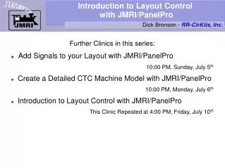
Introduction to Layout Control with JMRI/PanelPro Dick Bronson - RR-CirKits, Inc. • Further Clinics in this series: • Add Signals to your Layout with JMRI/PanelPro 10:00 PM, Sunday, July 5th • Create a Detailed CTC Machine Model with JMRI/PanelPro 10:00 PM, Monday, July 6th • Introduction to Layout Control with JMRI/PanelPro This Clinic Repeated at 4:00 PM, Friday, July 10th
Getting Started Preferences • Setting the PanelPro Preferences Setup your hardware according to the information found in the JMRI Help pages. Select 'Help' – 'General Help...' then navigate down to 'DecoderPro' – 'DecoderPro Manual' – 'Getting Started' – 'Setting Preferences'. On the web go to: http://www.jmri.org/help/en/manual/Getting_Started.shtml#Start • Note: The setup options for PanelPro are saved in their own startup file, distinct from those in DecoderPro. Normally you will use the same settings for both DecoderPro and PanelPro. Be sure to not try and run both PanelPro and DecoderPro at the same time. They are essentially the same program, so you have the full capabilities of each no matter how you initially start it running.
Getting Started Starting the Program • Use your own operating systems method for starting the program. In this demo we are running with Ubuntu Linux.
Getting Started Starting the Program • Use your own operating systems method for starting the program. In this demo we are running with Ubuntu Linux. • Select the desired startup icon and double click.
Getting Started Useful Information • The initial PanelPro window includes information about the version numbers of JMRI, Java, and also information about the computer interface. Include this information as well as your computer's operating system type in any support requests.
Getting Started Useful Information • The initial PanelPro window includes information about the version numbers of JMRI, Java, and also information about the computer interface. Include this information as well as your computer's operating system type in any support requests. • I have also added some extra shortcut buttons using the advanced preferences.
Getting Started Opening a new panel • To get started on building a panel open the 'Panels' drop down list and select 'New Panel'
Getting Started Choose your editor • This will open a selection between the 'Layout Editor' and 'Panel Editor'
Getting Started Choose your editor • This will open a selection between the 'Layout Editor' and 'Panel Editor' • The 'Layout Editor' is a vector based way to create a drawing that follows your layout plan and which auto captures much of the information required for Simple Signaling.
Getting Started Choose your editor • This will open a selection between the 'Layout Editor' and 'Panel Editor' • The 'Layout Editor' is a vector based way to create a drawing that follows your layout plan and which auto captures much of the information required for Simple Signaling. • The traditional 'Panel Editor' is a pure graphic based solution that is well suited to making classic CTC panels like we will do in this clinic.
Getting Started The new panel • Clicking on 'Panel Editor' will open two new windows.
Getting Started The new panel • Clicking on 'Panel Editor' will open two new windows. • The first is a small window containing a blank panel.
Getting Started The new panel • Clicking on 'Panel Editor' will open two new windows. • The first is a small window containing a blank panel. • The second is the Panel Editor control itself.
Panel Editor Panel Editor details • Panel Editor Details • Coordinates. These coordinates set the location where graphic objects will appear on the panel. The default is (0, 0) which is the upper left corner of the panel. Graphic objects are all referenced to their upper left corners.
Panel Editor Panel Editor details • Panel Editor Details • Coordinates. These coordinates set the location where graphic objects will appear on the panel. The default is (0, 0) which is the upper left corner of the panel. Graphic objects are all referenced to their upper left corners. • Click here to name our panel.
Panel Editor Panel Editor details • Panel Editor Details • Coordinates. These coordinates set the location where graphic objects will appear on the panel. The default is (0, 0) which is the upper left corner of the panel. Graphic objects are all referenced to their upper left corners. • Click here to name our panel. • Enter a name for our new panel, then click 'OK'.
Panel Editor Panel Editor details • Panel Editor Details • Coordinates. These coordinates set the location where graphic objects will appear on the panel. The default is (0, 0) which is the upper left corner of the panel. Graphic objects are all referenced to their upper left corners. • Click here to name our panel. • Enter a name for our new panel, then click 'OK'. • Our new name now shows at the top of the Panel Editor window.
Panel Editor Panel Editor details • Panel Editor Details • Coordinates. These coordinates set the location where graphic objects will appear on the panel. The default is (0, 0) which is the upper left corner of the panel. Graphic objects are all referenced to their upper left corners. • Click here to name our panel. • Enter a name for our new panel, then click 'OK'. • Our new name now shows at the top of the Panel Editor window. • Checkbox options. These 5 check boxes control various behaviors of the individual graphic icons that form the finished panel.
Panel Editor Panel Editor details • Panel Editor Details • Coordinates. These coordinates set the location where graphic objects will appear on the panel. The default is (0, 0) which is the upper left corner of the panel. Graphic objects are all referenced to their upper left corners. • Click here to name our panel. • Enter a name for our new panel, then click 'OK'. • Our new name now shows at the top of the Panel Editor window. • Checkbox options. These 5 check boxes control various behaviors of the individual graphic icons that form the finished panel. • This last checkbox will remove the panel's menu itself. Do NOT both uncheck this and close the editor without thinking 'Manual Edit'.
Panel Editor Background Images • Background Images • Click here to add a background to our panel. For experienced users of Panel Editor JMRI versions prior to 2.6 things will look a little bit different from here on.
Panel Editor Background Images • Background Images • Click here to add a background to our panel. For experienced users of Panel Editor JMRI versions prior to 2.6 things will look a little bit different from here on. • Next select 'Add Background'.
Panel Editor Background Images • Background Images • Click here to add a background to our panel. For experienced users of Panel Editor JMRI versions prior to 2.6 things will look a little bit different from here on. • Next select 'Add Background'. • A selection box opens with a default icon. We can click 'Add to Panel' or else 'Change icon..' to find something more suitable.
Panel Editor Background Images • Background Images • Click here to add a background to our panel. For experienced users of Panel Editor JMRI versions prior to 2.6 things will look a little bit different from here on. • Next select 'Add Background'. • A selection box opens with a default icon. We can click 'Add to Panel' or else 'Change icon..' to find something more suitable. • This opens up a selection box where we can drill down to the required images.
Panel Editor Background Images • Background Images • Click here to add a background to our panel. For experienced users of Panel Editor JMRI versions prior to 2.6 things will look a little bit different from here on. • Next select 'Add Background'. • A selection box opens with a default icon. We can click 'Add to Panel' or else 'Change icon..' to find something more suitable. • This opens up a selection box where we can drill down to the required images. • We will be mostly using images from the USS folder.
Panel Editor Background Images • Background Images • Click here to add a background to our panel. For experienced users of Panel Editor JMRI versions prior to 2.6 things will look a little bit different from here on. • Next select 'Add Background'. • A selection box opens with a default icon. We can click 'Add to Panel' or else 'Change icon..' to find something more suitable. • This opens up a selection box where we can drill down to the required images. • We will be mostly using images from the USS folder. • Clicking on 'background' will open up all the background images for drag and drop selection.
Panel Editor Background Images • Background Images • There are at least three ways to build a background for our panel. • Use a graphic editor to create your own complete panel image including plates.
Panel Editor Background Images • Background Images • There are at least three ways to build a background for our panel. • Use a graphic editor to create your own complete panel image including plates. • Choose a single or dual 15 position blank image then add individual plates for each position.
Panel Editor Background Images • Background Images • There are at least three ways to build a background for our panel. • Use a graphic editor to create your own complete panel image including plates. • Choose a single or dual 15 position blank image then add individual plates for each position. • Slices. This method takes advantage of the capability for panels to be constructed from multiple background images. We will use slices in this clinic.
Panel Editor Background Images Using Slices • Slices Prototype CTC panels used modular construction. Unused panel positions were simply blanked out with hole plugs. Slices are images of one panel position, usually controlling one signal plant. (interlocking) Each position may be blank, contain a switch plate, a signal plate, or both. Panel slices are available in three sizes, 718 pixles, 850 pixles, and 900 pixles high. The image names include a '-7', '-8', or '-9' in their names to distinguish them. Choose the tallest images that will fit in your screen size.
Panel Editor Background Images Using Slices • Slices • The slices are just two widths. 12 pixles wide for the panel edges, and 65 pixles wide for the modular sections. This allows the same icons to fit all the different height panels.
Panel Editor Background Images Using Slices • Slices • The slices are just two widths. 12 pixles wide for the panel edges, and 65 pixles wide for the modular sections. This allows the same icons to fit all the different height panels. • The first 'slice' of our panel will be the left edge. We will leave the (x, y) coordinates set to (0, 0) for this initial image. We will choose the shorter images to help conserve space for this presentation.
Panel Editor Background Images Using Slices • Slices • The slices are just two widths. 12 pixles wide for the panel edges, and 65 pixles wide for the modular sections. This allows the same icons to fit all the different height panels. • The first 'slice' of our panel will be the left edge. We will leave the (x, y) coordinates set to (0, 0) for this initial image. We will choose the shorter images to help conserve space for this presentation. • Note: The taller images have more room and, are closer to prototype proportions, so use them if possible.
Panel Editor Background Images Using Slices • Slices • To select an image, click on it and then drag it to the top of the Window.
Panel Editor Background Images Using Slices • Slices • To select an image, click on it and then drag it to the top of the Window. • Note that you will need to place the cursor directly on the image itself to grab the image.
Panel Editor Background Images Using Slices • Slices • To select an image, click on it and then drag it to the top of the Window. • Note that you will need to place the cursor directly on the image itself to grab the image. • Once you have selected the required slice, click on 'Add to Panel'.
Panel Editor Background Images Using Slices • Slices • To select an image, click on it and then drag it to the top of the Window. • Note that you will need to place the cursor directly on the image itself to grab the image. • Once you have selected the required slice, click on 'Add to Panel'. • This will place a full sized version of the image at (0, 0) in the panel window. It is 12 pixles wide.
Panel Editor Background Images Using Slices • Slices • To select an image, click on it and then drag it to the top of the Window. • Note that you will need to place the cursor directly on the image itself to grab the image. • Once you have selected the required slice, click on 'Add to Panel'. • This will place a full sized version of the image at (0, 0) in the panel window. It is 12 pixles wide. • Enlarge the window to show more of our panel as we go along.
Panel Editor Background Images Using Slices • Slices • Now pull up the editor window and change the ”x” axis value to '12' to move the starting location for the next slice to the right hand edge of the image that we just added. (the ”y” axis value remains unchanged)
Panel Editor Background Images Using Slices • Slices • Now pull up the editor window and change the ”x” axis value to '12' to move the starting location for the next slice to the right hand edge of the image that we just added. (the ”y” axis value remains unchanged) • The next slice we select will be a blank module which will give us some extra space at the panel's edge.
Panel Editor Background Images Using Slices • Slices • Now pull up the editor window and change the ”x” axis value to '12' to move the starting location for the next slice to the right hand edge of the image that we just added. (the ”y” axis value remains unchanged) • The next slice we select will be a blank module which will give us some extra space at the panel's edge. • As we can see in this view, our second slice has been positioned exactly next to the first one.
Panel Editor Background Images Using Slices • Slices • The 'blank' module includes images of the hole plugs used on the prototype panels at all unused positions.
Panel Editor Background Images Using Slices • Slices • The 'blank' module includes images of the hole plugs used on the prototype panels at all unused positions. • Now change the ”x” coordinate to 12+65 or 77 to properly position the next slice.
Panel Editor Background Images Using Slices • Slices • The 'blank' module includes images of the hole plugs used on the prototype panels at all unused positions. • Now change the ”x” coordinate to 12+65 or 77 to properly position the next slice. • This time we will choose a slice with both plates included. (Panel-sw-sig-7)
Panel Editor Background Images Using Slices • Slices • The 'blank' module includes images of the hole plugs used on the prototype panels at all unused positions. • Now change the ”x” coordinate to 12+65 or 77 to properly position the next slice. • This time we will choose a slice with both plates included. (Panel-sw-sig-7) • Add 3 more sections using coordinates x:142, x:207, and x:272 for the individual slices.
Panel Editor Background Images Using Slices • Slices • The 'blank' module includes images of the hole plugs used on the prototype panels at all unused positions. • Now change the ”x” coordinate to 12+65 or 77 to properly position the next slice. • This time we will choose a slice with both plates included. (Panel-sw-sig-7) • Add 3 more sections using coordinates x:142, x:207, and x:272 for the individual slices. • Our panel is taking shape, but it would be nice to have two blank sections on the left side.
Panel Editor Background Images Using Slices • Slices • Start by enabling the coordinates in popup menus. This will help us know where our slices are located, and allow us to move them easily.
Panel Editor Background Images Using Slices • Slices • Start by enabling the coordinates in popup menus. This will help us know where our slices are located, and allow us to move them easily. • Next right click in the slice image that we need to move. This opens the popup menu showing the current coordinates.
Panel Editor Background Images Using Slices • Slices • Start by enabling the coordinates in popup menus. This will help us know where our slices are located, and allow us to move them easily. • Next right click in the slice image that we need to move. This opens the popup menu showing the current coordinates. • Click on 'Set Location'
Panel Editor Background Images Using Slices • Slices • Start by enabling the coordinates in popup menus. This will help us know where our slices are located, and allow us to move them easily. • Next right click in the slice image that we need to move. This opens the popup menu showing the current coordinates. • Click on 'Set Location' • This opens a new window where we can change the location of this slice. (337,0) is the next position. Write down the original values for later. Click 'Set' to move the slice.
Panel Editor Background Images Using Slices • Slices • The slice has been moved to where we need it, but leaving a empty position.