Download
1 / 29
290 likes | 378 Views
Learn how advanced modeling and response surface methodology are applied to construct physical models for Level 2 PSA, using validated codes with examples like Direct Containment Heating and Ex-vessel steam explosion.

E N D
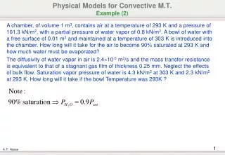
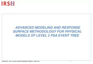
ADVANCED MODELING AND RESPONSE SURFACE METHODOLOGY FOR PHYSICAL MODELS OF LEVEL 2 PSA EVENT TREE
Plan • The physical models of the APET • Principle of the method • Construction of a “physical model” • Comments • Example of Direct Containment Heating Model • Example of Ex-vessel steam explosion Model • Example of Containment thermo-mechanical Model
Introduction • For level 2 PSA and the construction of the APET, the IRSN has opted to use, as far as possible, results obtained directly from validated physical codes • One aim is to take benefit of R&D investments in the development and validation of severe accident codes • Three examples from the 900 MW level 2 PSA are provided
Before Core degradation Vessel Rupture During Core degradation Corium-Concrete Interaction I- SGTR In-vessel steam explosion Combustion Before core degradation Advanced core degradatio Level 1 PSA Plant Damage State During Core Degradationn Ex-vessel s.e. Corium concrete interaction Combustion H2 Direct Containt Heating Containment mechanical behavior The physical models of the Accident Progression Event Tree
Principles for construction of physical models • Physical models of APET must : • 1- give a “best-estimate” evaluation of a physical phenomenon and of its consequences • 2- take into account uncertainties • 3- be very fast • 4- replace sophisticated codes used for severe accident with relative accuracy
Upstream • uncertain variables Physical model RVk = F (SVi , UVj) Upstream state variables Downstream Results Variables Schema of a physical model
Definitions • UPSTREAM “STATE”VARIABLES • They provide relevant information on the plant state for the evaluated physical phenomena : physical conditions (RCS pressure e.g.) or systems information (pressurizer valve aperture e.g.) • Generally, they come from previous APET model or PDS variables • UPSTREAM “UNCERTAIN”VARIABLES • They are defined by probabilities distribution ; a value is assigned by sampling via a Monte-Carlo method • They can have different origins : • Parameter of sophisticated code not well known but with strong impact on results ; • Expert’s judgment on the accuracy of code result • Statistical uncertainties due to the construction of the APET physical model • DOWNSTREAM “RESULTS” VARIABLES
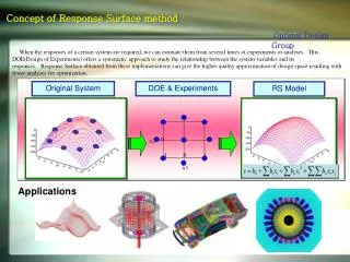
Construction of a « physical model » « SOPHISTICATED SEVERE ACCIDENT CODE » CALCULATIONS APET Requirements • 3 STEPS • Choice and hierarchy of upstream variables • Elaboration of a response surface for each downstream variables • Validation of the response surface accuracy Experimental design
Construction of a “physical model” • STEP 1 : CHOICE AND HIERARCHY OF UPSTREAM VARIABLES • Experts provide a first list of upstream (state or uncertain) variables ; for each variable a possible interval of variation is defined • A first experimental design is defined : each variable can take the extreme values of its variation interval • For each variables combination of the experimental design, a calculation of downstream variables is led with the sophisticated code • A statistical analysis is achieved for each downstream variable • A hierarchy between upstream variables is established ; some of them may be eliminated
Construction of a “physical model” • STEP 2 : ELABORATION OF A RESPONSE SURFACE FOR EACH DOWNSTREAM VARIABLE • A second experimental design plan is defined with more possible values of each upstream variable • For each combination of variables values obtained in the experimental design plan, a calculation of downstream variables is realized with the sophisticated code • For each downstream variable, the best response surface of upstream variables is constructed with a statistical analysis (minimal regression) • The statistical uncertainties of the response surface are estimated
Construction of a “physical model” • STEP 3 :VALIDATION OF THE RESPONSE SURFACE ACCURACY • Other calculations with the sophisticated code are made with new combinations of upstream variables values, • Results are compared to the response surface • The first and second steps are completed if the accuracy of the response surfaces is not sufficient
Comment • This methodology has to be adapted to each case : • the number of runs with a sophisticated code depends on its execution speed • a physical and a statistical approach must be associated for the construction of the response surface
Enceinte Corium + Vapeur d’eau + H2 Espace Annulaire Puits de cuve Compartiment Intermédiaire Example 1Direct Containment Heating « sophisticated code » RUPUICUV CPA (ASTEC system)
Example 1Direct Containment Heating – STEP 1 • Upstream • uncertain • variables • Corium particles diameter • Heat exchange coefficient between corium particles and containment atmosphere • Average flying delay of the corium particles in containment • Vessel heat insulator state • Duration of hydrogen combustion Upstream state variables DCH model RVk = F (SVi , UVj) • Mass of dispersed corium • Pressure peak in containment • Vessel pressure • Mass of melt-corium Downstream Results Variables
Example 1Direct Containment Heating – STEP 2 • Dispersed corium mass in function of upstream variables : • Correlation derived from experiments (KAERI) • Uncertainties are issued from the analysis of results on the KAERI tests
Example 1Direct Containment Heating – STEP 2 • Pressure peak : 144 CPA-RUPUICUV runs defined by 2 experimental designs (9 lines for upstream variables that impact dispersed corium mass, 16 lines for other variables)
Example 1Direct Containment Heating – STEP 3 • Final validation has shown that the pressure peak is underestimated around 8 bar. • This has been checked on sensitivity analyses. • 0.3 bar is added to the analytical calculation of pressure peak to guarantee conservatism.
Vessel Containment wall 2d Floor 1st Floor Wall Vessel Pit Example 2Ex-vessel steam explosion model • Water can be present in the vessel pit after use of spraying system (CHRS) • Consequences of Corium-Water Interaction ?
Example 2Ex-vessel steam explosion model • MC3D code : pre-mixing of corium and water • explosion • EUROPLEXUS : damage on the structures
Example 2Ex-vessel steam explosion model – STEP 1 Upstream uncertain variables Water height Water temperature Best-estimated Parameters Vessel Pressure Corium overheat Vessel breach diameter Containment failure probability N calculations of structure displacement Pre-mixing N Steam Explosion Runs Results if no steam explosion Upstream state variables
Example 2Ex-vessel steam explosion model – STEP 2 • The probability of steam explosion is not evaluated • For each pre-mixing conditions, up to 50 steam explosions are achieved • In function of structure displacement calculated for each explosion, pre-mixing conditions are associated to one category that corresponds to a probability of containment failure • After a statistical analysis, a mathematical expression estimates the containment failure probability as a function of upstream variables
Example 3Containment thermo-mechanical model • The APET model has to predict a containment leak size according to pressure and thermal loading • PWR 900 MW containment building : • Structure : basemat, cylinder and dome • Prestressed reinforced concrete • 6 mm thick steel liner covers the inner surface of the containment • Design pressure limit 0.5 Mpa • Three steps of modeling with CAST3M code have been performed
Example 3Containment thermo-mechanical model • A 3D 360 ° for initial containment building state (30 year aged), effect of structure weight, prestressing system with relaxation in tendon and concrete creep and shrinkage Prestressed tendons Passive steel Concrete
Example 3Containment thermo-mechanical model • A 3D 90° model calculates the non linear behavior of the containment in function of thermal and pressure loading ; • initial conditions come from the 3D 360° model
Example 3Containment thermo-mechanical model • A 3D local model for equipment hatch ; boundary conditions of this local model come from the 3D 90°model
Example 3Containment thermo-mechanical model • One reference severe accident loading is used (with sensitivity case) H2 burning Safety injection failure Melt-corium interaction (MCCI) SCRAM
Example 3Containment thermo-mechanical model • Analysis of results shows that : • the containment leak resistance depends on steel liner integrity because cracks appear quite early in the concrete • experts have used NUPEC-NRC-SANDAI PCCV tests to define local criteria for liner rupture • The conclusion is that the liner rupture may occur at around 1 MPa • local calculation of equipment hatch have confirmed that it is a critical part of the structure : • mechanical contact between the flanges of the equipment hatch closing system may be lost at a pressure not far above the containment design pressure with current screws • containment tightness depends then only on the seal efficiency which could be damaged by radiation
Example 3Containment thermo-mechanical model • The APET model only takes into account the leakage through the equipment hatch : A parameter to take into account uncertainties on leakage size calculation Containment model Pressure Peak in containment Containment leakage size Uncertainties are discussed in the frame work of an expert’s group
Conclusion • A GENERAL METHODOLOGY FOR PHYSICAL MODEL OF APET • ONE MODEL FOR ONE PHENOMENA • USE OF VALIDATED CODE AS FAR AS POSSIBLE • GRID METHOD WHEN HIGH DISCONTINUITIES EXIST (CORE DEGRADATION) • RESPONSE SURFACES METHODOLOGYWITH « STATE » AND « UNCERTAIN » UPSTREAM VARIABLES • AN ADAPTED APPROACH TO EACH CASE • EXPERT’S JUDGMENT USED FOR RESULTS INTERPRETATION AND FINAL APET MODEL CONSTRUCTION • THE METHODOLOGY REQUIRES LARGE SENSITIVITIES STUDIESUSEFUL FOR UNCERTAINTIES ANALYSIS