Download
1 / 43
430 likes | 443 Views
Explore the creation and printing of 3D models to aid in understanding mathematical concepts. Learn about the challenges and possibilities of using 3D printing technology in math education.

E N D
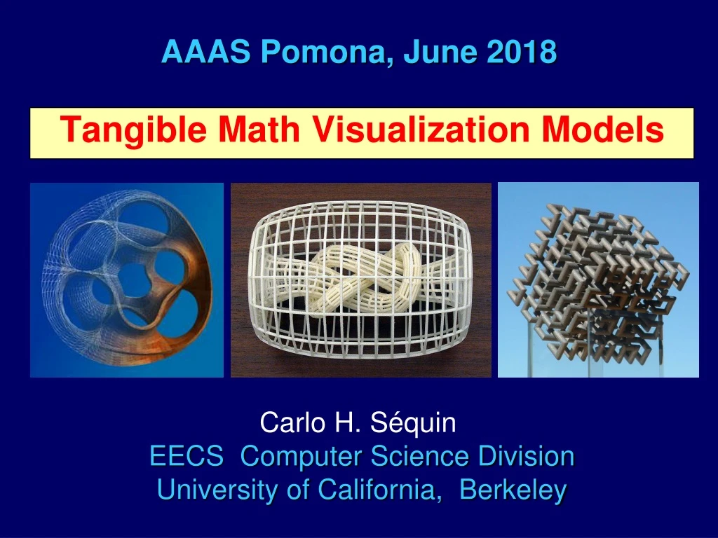
AAAS Pomona, June 2018 Tangible Math Visualization Models Carlo H. Séquin EECS Computer Science Division University of California, Berkeley
Motivation • Helaman Ferguson: “Sculptures are meant to be touched!” Some geometrical / topological mathematical concepts are easier to understand, if you can run your fingers along a physical model.
Creating a 3D (Math-) Model • Phase ONE: Create a CAD ModelThis is NOT trivial and it is time-consuming. • Use tools such as: Blender, Maya, Sketchpad … • Augment them with your own software,written in Java, Python, C++ … • Phase TWO: Obtaining a 3D-Print ModelRequires some luck, or money, or both. • Use a low-end printer in some Maker-Space:Many different failure modes, manual clean-up! • Send CAD model to https://www.shapeways.com/This costs some $$; one week turn-around.
Installation at MWSU, Feb. 2013 “Music of the Spheres” Steve Reinmuth Brent Collins
Ribbon Sculptures Altamont Stelvio Collins: Pax Mundi(1994)
SLIDE-GUI for “ViaeGlobi” Shapes Good combination of interactive 3D graphicsand parameterizable procedural constructs.
Sweep Curve Generator: Gabo Curves as B-splines: Cross Section Fine Tuner: Parameterized shapes: Sweep / Twist Controller: How is cross section applied? Modularity of Gabo Sweep Generator
Applying the cross section: Azimuth / Twist Control azimuth = 0, azimuth = 90, azimuth = 90, twist = 0; twist = 0; twist =180;
Controls applied to the 2-period Gabo curve: Azimuth / Twist Control Torsion Minimization:Azimuth: tangential / normal 900 of twistadded. Natural orientationwith Frenet frame
Extension: Free-form Curve on a Sphere Spherical Spline Path Editor (Jane Yen) Nice smooth interpolating curves through sparse data points
Many Different Viae Globi Models Maloya Stelvio Altamont
Extending the Paradigm:Aurora-M • Simple path on sphere, • but more play with the swept cross section. • This is a Möbiusband. • It is morphed from a concave shape at the bottom to a flat ribbon at the top of the flower. “Sweep-Morph”
Paradigm Extension:Sweep Path is no longer confined to a sphere! Chinese Button Knot ( K-940 )
ChineseButton Knot(Knot 940)Bronze, Dec. 2007Carlo Séquincast & patina bySteve Reinmuth
“Hollow” by Eva Hild, Varberg, 2006 This is a design task, where I felt it necessary to develop my own rudimentary CAD software…
Sculptures Defined by Key Features RimsFunnelsTunnels Marked features:
“NOME”Non-Orientable Manifold Editor Place key features: Rims, Funnels, Tunnels; Connect their borders with surface patches; Smooth the assembly with CC-subdivision; Use offset-surfaces to thicken the 2-manifold; Create finely tessellated B-rep (.STL-file); Send to 3D-Printer.
Computer-Aided Design Process Modeling “Interruption” 3D-print
Room for Improvement Here the tunnel is not as nicely roundedas in Hild’s original.
An Improved NOME Model Two more tunnels added.
How to Get a 3D Print? • Save CAD model to an “.STL”-file. • a wasteful representation of your geometry (all cut up into little triangles). • But it is the “lingua franca” of all 3D printers! • Take it to a low-end printer in a Maker-Space. • Hope that the printer will do its job . . .
Possible Results . . . or You want to get this: You may get this:
Imperfect Surfaces There may be ridges where the support structure touched the desired shape. Or the printer may just spew out a little more plastic than needed, creating ugly bumps.
Finally – A Good Print Try different parameter settings: Try different build orientations, Try different bases (“raft” vs. just “brims”), Try different support structures (“lines” / “grids”), Try a reduced print speed, Other options … You may get this:
Pass the Headaches to Someone Else Use an on-line print service, e.g.shapeways: https://www.shapeways.com/ Send a design to their web site; Select a material and a size for the 3D-print; Get a quote within minutes; Pay by credit card; Get your part within a week.
Many Different Materials . . . Ceramic Metal Plastic Plaster
“Wolly” by Eva Hild Free-form surfaces offer a bigger modeling challenge!
Topology of “Wholly” 2-sided, single border, genus 4
A Flexible, Parameterized Model Polyhedral model, with high-level edit-controls
First, Not Very Successful Attempt An FDM model of “Wholly” ?
Second Attempt with Same Set-Up Wholly_A2: a more carefully tuned model
Comparison Wholly_A1 Wholly_A2 Tunnels still not very round
Trying a New Approach Combining 8 partial toroids into a flexible chain
Parameterization (2D concept proof) Radii, heights, azimuth angles, tilt are adjustable. Automatic adjustment of tunnel/tunnel separation.
Resulting 3D CAD Model Wholly_B1
First Result from the New Approach Wholly_B1 coming off the 3D printer
Model after Clean-up Wholly_B1
Comparison Wholly_A2 Wholly_B1 Roundtunnels. Other problems!
Orientability Moebius band Cooling tower Hild: “Interruption” Dyck loop 2-sided, 1-sided,orientable non-orientable
Not a “Hild Sculpture” Tetrahedral configuration of 6 “Super Dyck disks” with 4 stubs