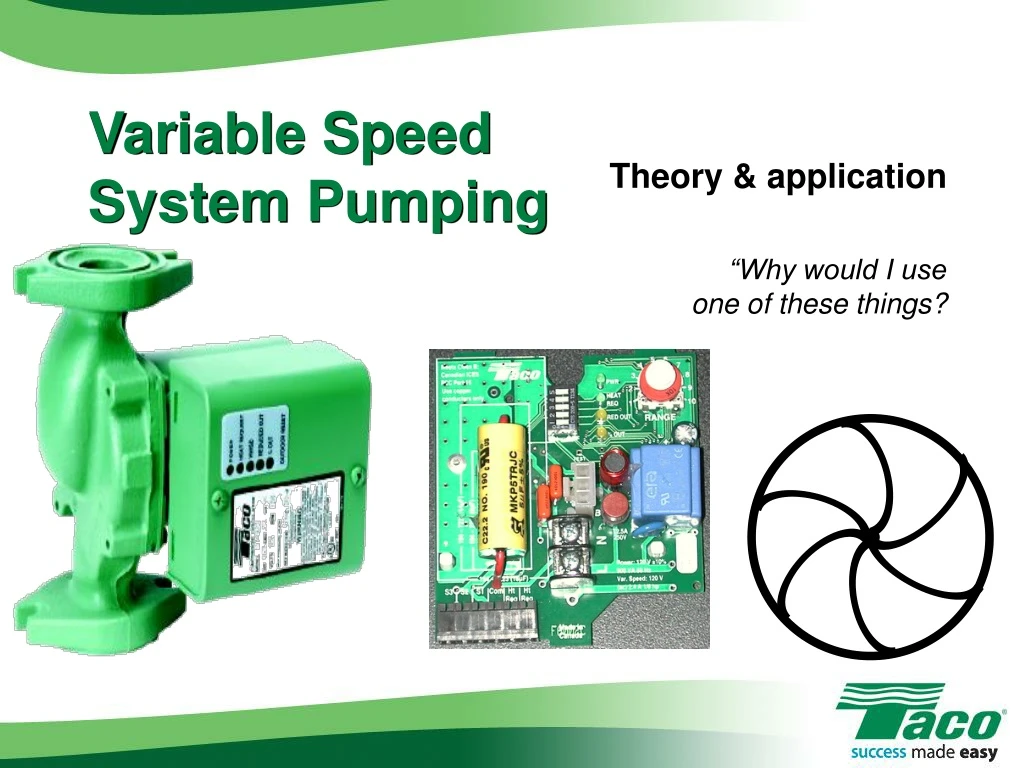

Variable Speed System Pumping
E N D
Presentation Transcript
Variable Speed System Pumping Theory & application “Why would I use one of these things?
Why Use a Variable Speed Circulator? • Good question… • What do they do? • Vary speed based on changing loads • Use external information • Best applications… • System circulator with zone valves • Radiant with multiple zoneson single manifold using actuators
Universal Hydronics Formula • GPM = BTUH ¸DT x 500 • GPM = Gallons per minute • BTUH = Heating load • DT = Design temperature drop • 200 for baseboard • 100 for radiant • 500 = 8.33 x 60 x 1
Sample Project • Heat loss = 75,000 BTUH • Design temp = 00 • 3 zones fin tube • 25K BTUH each • 200DT
Do The Math! • GPM = BTUH ¸DT x 500 • GPM = 75,000 • GPM = 75,000 • GPM = 7.5 20 x 500 10,000
For Each Zone… • 25,000 BTUH each • GPM = 25,000 • GPM = 25,000 • GPM = 2.5 per zone 20 x 500 10,000
Pipe Sizing • 2-4 GPM = ¾” pipe • 4-8 GPM = 1” pipe • 8-12 GPM = 1¼” pipe • 12-22 GPM = 1½” pipe • Min/max velocity • 2-4 FPS • > 4 = velocity noise
¾” 1” Let’s Pipe ‘Er Up!
Head Loss 150’, including element
Head Loss • Longest run = 150’, including element • Multiply by 1.5 to allow for fittings, etc • 150 x 1.5 = 225’ • Multiply by .04 • 4’ head/100’ of pipe • 225 x .04 = 9’ head loss • 7.5 GPM @ 9’ head
15 10 5 5 20 10 15 Pick The Pump… Taco 008 Pump Curve 9’ Head 7.5 GPM
15 10 5 5 20 10 15 System Curve System Operating Point – All Zones Calling
15 15 10 10 5 5 5 5 20 20 10 10 15 15 As Zone Valves Close… System Operating Point – 2 Zones Calling System Operating Point – 1 Zone Calling 4 GPM 6.5 GPM
GPM = BTUH 6.5 = 50,000 DT is lower than design Poor heat transfer Less efficient boiler Velocity noise 15 10 5 5 20 10 15 As Zone Valves Close… System Operating Point – 2 Zones Calling DT x 500 DT x 500 DT 6.5 GPM
So What Do We Do About It? • Ignore it? • “That’s just the way these systems are!”
15 System Operating Point – All Zones Calling 10 5 5 20 10 15 A Better Solution… • Variable speed pumping! Actual flow rate » 9 GPM
GPM = BTUH BTUH = GPM x DT x 500 DT = BTUH DT = 75,000 DT = 160 DT w/2 zones = 150 DT w/1 zone = 120 Under DESIGN conditions! ¸ 500 ¸ 500 GPM 9 Universal Hydronic Formula DT x 500
But What If DT Was Fixed? • GPM = BTUH • GPM = 75,000 • GPM = 7.5 • The flow will vary! DT x 500 = 50,000 = 25,000 DT x 500 20 5 2.5
15 10 5 5 20 10 15 A Better Solution…
An Important Consideration… • Calculate max flow rate • Estimate head loss • Length X 1.5 X .04 • Head loss at MAX flow rate • Actual flow rate much less • Can overestimate head by 50% • DT circulator “self-adjusts”
Taco 00-VDT • Variable speed DT circulator • Control built in • Simple to install • Simple to program • Simple to understand! • 008, 0012, 0013 VDT
A Simple Solution 00-VDT
Setting It Up… • Dip Switches • Switch 1, 3 ON • All others OFF • Range Dial • Adjust to desired DT
Supply Sensor Supply Sensor Return Sensor Return Sensor Wiring It Up… • H-N to ZVC • Supply sensor to S2 & Com • Return sensorto S1 & Com
Some Parting Thoughts… • ΔT directly related to flow rate • Pump speed adjusts to required BTU/hr • ΔT ensures optimum performance BB, radiant, etc • ΔT does not “flat line” • ΔT always runs at lowest required speed • Lots of models • EASY to set up!