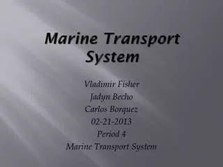
MARINE PUMPING SYSTEM
MARINE PUMPING SYSTEM. SPECIFIC LEARNING OBJECTIVES:. At the end of this topic you are expected to learn: Principles of Marine Pumping Systems State the function of a pump Describe the three requirements for a pump to transfer fluids List the losses of head in a pumping system

MARINE PUMPING SYSTEM
E N D
Presentation Transcript
SPECIFIC LEARNING OBJECTIVES: At the end of this topic you are expected to learn: • Principles of Marine Pumping Systems • State the function of a pump • Describe the three requirements for a pump to transfer fluids • List the losses of head in a pumping system • Explain the requirement for viscosity of the fluid for pump design
Explain the requirement for permission before any fluid is transferred onboard
Pumping System have two main purposes: • Transfer of liquid from one place to another place (e.g. water from an underground aquifer into a water storage tank) • Circulate liquid around a system (e.g. cooling water or lubricants through machines and equipment)
PUMP • A pump is a device used to move fluids, such as liquids, gases or slurries. • A pump displaces a volume by physical or mechanical action. Pumps fall into three major groups: direct lift, displacement, and gravity pumps.[1] Their names describe the method for moving a fluid.
PUMP • Def’n: device that uses an external power source to apply force to a fluid in order to move it from one place to another • Must overcome: • (1) frictional forces from large quantities of fluid • (2) difference in static pressure between two locations • Must provide any velocity desired
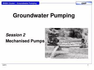
MARINE PUMP • A device use aboardship which adds energy to a liquid or gas to overcome resistance or system losses causing it to generate pressure and perhaps movement of a fluid • A machine used to raise fluid from a low point to a high point
Engine – a device for converting thermal energy of working substance into useful mechanical work • Marine pumps generally handle fuel oil, lubricating oil, condensate and boiler feed, circulation water or coolant, ballast and bilge water, air, etc. though pumps delivering air are generally called blowers or compressors. • Special liquid cargoes of nearly or any sort may be handled by a suitable pump. Depending upon the types of installation, pumps are driven by steam engines, steam, electric motors, Diesel engines and air.
Pumps can also be found coupled with engine it supports. Motive power is selected for reasons of safety, economics or convenience.
Fluid Properties • The properties of the fluids being pumped can significantly affect the choice of pump. Key considerations include: • Acidity/alkalinity (pH) and chemical composition. Corrosive and acidic fluids can degrade pumps, and should be considered when selecting pump materials. • Operating temperature. Pump materials and expansion, mechanical seal components, and packing materials need to be considered with pumped fluids that are hotter than 200°F. • Solids concentrations/particle sizes. When pumping abrasive liquids such as industrial slurries, selecting a pump that will not clog or fail prematurely depends on particle size, hardness, and the volumetric percentage of solids.
Fluid Properties • Specific gravity. The fluid specific gravity is the ratio of the fluid density to that of water under specified conditions. Specific gravity affects the energy required to lift and move the fluid, and must be considered when determining pump power requirements. • Vapor pressure. A fluid’s vapor pressure is the force per unit area that a fluid exerts in an effort to change phase from a liquid to a vapor, and depends on the fluid’s chemical and physical properties. Proper consideration of the fluid’s vapor pressure will help to minimize the risk of cavitation.
Fluid Properties • Viscosity. The viscosity of a fluid is a measure of its resistance to motion. Since kinematic viscosity normally varies directly with temperature, the pumping system designer must know the viscosity of the fluid at the lowest anticipated pumping temperature. High viscosity fluids result in reduced centrifugal pump performance and increased power requirements. It is particularly important to consider pump suction-side line losses when pumping viscous fluids.
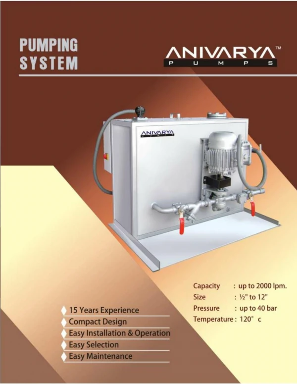
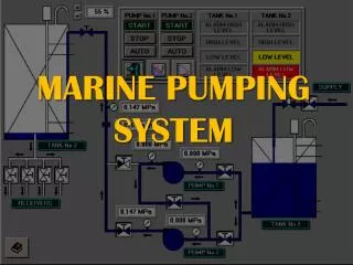
3 REQUIREMENTS OF A PUMP TO TRANSFER FLUID • A marine pumping system on a ship consists of: • Suction piping • Pump • Discharge piping • The system is arranged to provide a positive pressure or head at some point and discharge the liquid. The pump provides the energy to develop the head and overcome any losses in the system. • The rate of flow at a certain head is called duty point.
PUMP HEAD • Head is a measure of resistance to flow. If a pump has a maximum output of 20 head feet, it means it can pump water 20' straight in the air. If a pump is rated at 50 gallons per minute at 10 feet it means it can overcome 10 feet of head (TDH) and still deliver 50 GPM. As you increase the head, you decrease the flow rate, and increase your operating costs. To maximize your flow, you must minimize your head, which also minimizes your operating costs.
3 MAIN SOURCES OF HEAD: • Static Head - This is the vertical distance you raise the water. To determine your static head, measure from the surface of the tank (vertically), to the highest point in the discharge line where the water is discharged to the atmosphere.
3 MAIN SOURCES OF HEAD: • Friction Head - As water flows through pipe and fittings there is resistance. The higher the flow and/or the smaller the pipe, the higher the resistance. Determine your overall pipe length, including adding in the equivalent length for your fittings. Consult the friction loss chart. Find where the column for your pipe diameter intersects the row for your flow rate and read the friction loss per 100' pipe. Use large enough pipe to minimize friction loss. It is usually best to keep your friction loss (per 100 feet of pipe) to less than 6 feet. In other words, once you know the desired flow rate, pick a pipe diameter, or schedule, that will give you less than 6 feet of friction loss per 100 feet of pipe. (Friction Loss and Fittings Loss)
3 MAIN SOURCES OF HEAD: • Pressure Head - Any additional pressure required by filters, spray nozzles, etc. must be calculated. The conversion is 1 PSI = 2.31 head feet. - Atmospheric pressure: usually refers to the pressure in the local environment of the pump. Atmospheric pressure varies with elevation, it is 14.7 psi at sea level and decreases with rising elevation. If our filter runs at 10 PSI, that would add 23.1 feet of head to the 17.9 feet required to overcome the friction loss of our pipe and fittings. So now the total pump head is 41 feet without considering the static head. (Notice that the pump head will increase as the filter gets dirty and increases the back pressure.)
3 MAIN SOURCES OF HEAD: • Total dynamic head ( TDH) – Sum of static head, friction loss head, fittings loss head, and pressure head.
3 MAIN SOURCES OF HEAD: • Don't forget to add up the equivalent feet of pipe for all the fittings. Now that you know your flow and head, you can select a pump that provides this performance, and does so efficiently.
Losses of Head in Pumping System • Power supplied to the pump must take into account the various losses. These are made up of: • Friction Loss in bearings and glands, surfaces of impeller and casing. Impellers should be highly polished to minimize friction loss. • Head Loss in pump due to shock at each entry and exit to impeller vane where eddies are formed at vane edges. • Leakage loss in thrust balance devices, gland sealing, clearances between cutwater and casing and bearing seals.
Requirement for Viscosity of the Fluid for Pump • Viscosity - the property of a fluid or semifluid that causes it to resist flowing • Oil are much more difficult for pumps to handle than water. Losses increase within the pump and pump lines. Both head and capacity are reduced; therefore more power is required for operation. • Both hot and thick liquids should flow to the pump under a positive suction head (flow by gravity) for satisfactory operation. The pump will then be kept properly primed in the case of thick liquids; vaporization and vapour binding will be avoided in the case of hot liquids.
Requirement for Viscosity of the Fluid for Pump • The problem of lifting a hot liquid is often difficult. The hotter the liquid, the lower will be the maximum possible suction lift. Water boils at 100 C atmospheric pressure. Under the partial vacuum that exists in the feed pipe, the boiling point is lower. Part of the hot water may vaporize causing vapour binding in the pump. In some cases the water vaporizes and expands sufficiently to destroy the vacuum thereby, stops the effectiveness of pumping.
Requirement for Viscosity of the Fluid for Pump • When pumping hot oil, it may happen that a small amount of water entrained in the oil may flash (boil) and interrupt the pumping operation. This can be serious in the case of a fuel oil service pump, as it may cause a “flare back” from the boilers. Providing an air chamber on the discharge line which will maintain a pressure while the pump is compressing the vapour in the line, can guard this against other precautions may be taken.
Requirement for Viscosity of the Fluid for Pump • Here is what is going to change when you pump viscous fluids with a centrifugal pump: • The brake horsepower requirement will increase. • You will notice a reduction in the head the pump will produce. • Some reduction in capacity will occur with moderate and high viscosities. • The pump's efficiency will decrease.
Requirement for Viscosity of the Fluid for Pump • High viscosity fluids are better handled with positive displacement pumps that are affected differently than centrifugal pumps by a change in fluid viscosity: • At a constant speed, changes in viscosity will have very little affect on capacity. • The total head will probably increase with viscosity because of higher system resistance. • The brake horsepower (kilowatts) will increase with capacity. • The efficiency probably will not be affected because of less leakage through the internal pump clearances. In some cases the efficiency will increase
Pre-Bunker Checklist: Pre-Bunkering Procedure: 1. State of adjacent waters noticed 2. Vessel properly secured to dock 3. Check suppliers product corresponds to ordered product 4. Agree quantity to be supplied 5. Check valves open 6. Day tanks full and supply valves closed 7. Warning signs in position e.g. No Smoking 8. SOPEP plan available
9. Clean up material in place 10. Oil Boom in place 11. Foam fire extinguisher placed at bunker station 12. Alfa Laval and transfer pumps off 13. Fuel tank supply valves open 14. Agree stop/start signals between vessel and barge/truck 15. Bravo flag flying/red light showing 16. Agree pumping/transfer rate 17. Agree emergency shut down procedure 18. Specification sheet received
19. Check hose and couplings are secure and in good order 20. Fuel nozzle and hose secured to vessel 21. Check barge/truck meters Reading: 22. Check on board meters Reading: 23. Bunker Valve open 24. Unused manifold connections blanked off 25. Master informed 26. Signal pumping to commence The above checklist has to be completely filled legibly by both the ship & barge personnels.
SOPEP equipments • At the bunker manifold and wherever necessary, as per the ships SOPEP plan, the SOPEP equipments should be kept in immediate readiness in order to avoid oil spill/pollution during bunkering operation.
SOPEP- Shipboard Oil Pollution Emergency Plan. SOPEP- Shipboard Oil Pollution Emergency Plan. The SOPEP Locker must have minimum of the below specified items: 1. absorbent roll 2. absorbent pads 3. absorbent granules 4. absorbent materials 5. brooms 6. shovels 7. mops 8. scoops 9. empty receptacles (200 ltrs capacity) 10. portable air driven pumps 11. oil boom 12. oil spill dispersants.
During Bunkering Procedures: During Bunkering checklist: 1. Witness taking and sealing of 2 representative product samples 2. Monitor fuel connections for leaks fuel flow and control tank levels 3. Change over of tanks whenever necessary. 4. Checking the rate at which bunkers are received. 5. Checking the tightness/slackness of mooring ropes. 6. Checking trim/list of the bunker barge & the ship. 7. Continuous monitoring/look outs for the vessel's position(when at anchor). During bunkering, the above checklist must be filled up and continuous monitoring of the above specified items are required till the bunkering operation is complete.
After Bunkering Procedures: On completion of the bunkering operations, with the ship-barge co-ordination, the line should be blown with air to make sure the line is not filled with oil. The after-bunker checklist is followed. After Bunker Checklist: 1. Bunker Valve closed 2. Disconnect hose (drain before disconnecting) 3. Check barge/truck meter Reading: 4. Check ships meter Reading:
5. Sign Bunker Delivery Receipt BDR No.:(Bunker Delivery Report/Note). 6. Retain BDR with product sample 7. SOPEP plan returned to bridge 8. Clean up gear stowed / Oil boom returned 9. Bravo Flag/Red light stowed/switched off 10. Remove and pack away warning/safety signs 11. Foam fire extinguisher placed back in correct location 12. Complete Oil Record Book 13. Master informed of completion 14. Confirm in Oil Record Book Bunkering checklist completed
Glossary in Pumps and Pumping System • Fluid - any substance that undergoes a change in pressure, temperature or volume used as means to carry out a thermodynamic process or cycle • Cavitation: the collapse of bubbles that are formed in the eye of the impeller due to low pressure. The implosion of the bubbles on the inside of the vanes creates pitting and erosion that damages the impeller. The design of the pump, the pressure and temperature of the liquid that enters the pump suction determines whether the fluid will cavitate or not.
Glossary in Pumps and Pumping System • Centrifugal force: A force associated with a rotating body. In the case of a pump, the rotating impeller pushes fluid on the back of the impeller blade, imparting circular and radial motion. A body that moves in a circular path has a centrifugal force associated with it . • Dead head: a situation that occurs when the pump's discharge is closed either due to a blocage in the line or an inadvertently closed valve. At this point, the pump will go to it's maximum shut-off head, the fluid will be recirculated within the pump resulting in overheating and possible damage. • Diffuser: located in the discharge area of the pump, the diffuser is a set of fixed vanes often an integral part of the casing that reduces turbulence by promoting a more gradual reduction in velocity.
Glossary in Pumps and Pumping System • Efficiency:: the efficiency of a pump can be determined by measuring the torque at the pump shaft with a torque meter and then calculating the efficiency based on the speed of the pump, the pressure or total head and flow produced by the pump. The standard equation for torque and speed provides power. • Absolute pressure: pressure is measured in psi (pounds per square inch) in the imperial system and kPa (kiloPascal or bar) in the metric system. Most pressure measurements are made relative to the local atmospheric pressure. In that case we add a "g" to the pressure measurement unit such as psig or kPag. The value of the local atmospheric pressure varies with elevation.
Glossary in Pumps and Pumping System • It is not the same if you are at sea level (14.7 psia) or at 4000 feet elevation (12.7 psia). In certain cases it is necessary to measure pressure values that are less then the local atmospheric pressure and in those cases we use the absolute unit of pressure, the psia or kPa a. pa(psia) = pr(psig) + patm(psia), patm = 14.7 psia at sea level. where pa is the absolute pressure, pr the relative pressure and patm the absolute pressure value of the local atmospheric pressure.
Glossary in Pumps and Pumping System • Accumulator: used in domestic water applications to stabilize the pressure in the system and avoid the pump cycling on and off every time a tap is opened somewhere in the house. • Affinity laws: the affinity laws are used to predict the change in diameter required to increase the flow or total head of a pump. They can also predict the change in speed required to achieve a different flow and total head. The affinity laws can only be applied in circumstances where the system has a high friction head compared to the static head and this is because the affinity laws can only be applied between performance points that are at the same efficiency. • Axial flow pump: refers to a design of a centrifugal pump for high flow and low head. The impeller shape is similar to a propeller. The value of the specific speed number will provide an indication whether an axial flow pump design is suitable for your application
Glossary in Pumps and Pumping System • Baseplate: all pumps require some sort of steel base that holds the pump and motor and is anchored to a concrete base. • Best Efficiency Point (B.E.P.): The point on a pump's performance curve that corresponds to the highest efficiency. At this point, the impeller is subjected to minimum radial force promoting a smooth operation with low vibration and noise. • Bingham plastic: A fluid that behaves in a Newtonian fashion (i.e. constant viscosity) but requires a certain level of stress to set it in motion. • Bourdon pressure gauge: the Bourdon tube is a sealed tube that deflects in response to applied pressure and is the most common type of pressure sensing mechanism.
Glossary in Pumps and Pumping System • Check valve: a device for preventing flow in the reverse direction. The pump should not be allowed to turn in the reverse direction as damage and spillage may occur. Check valves are not used in certain applications where the fluid contains solids such as pulp suspensions or slurries as the check valve tends to jam. A check valve with a rapid closing feature is also used as a preventative for water hammer. • Chopper pump: a pump with a serrated impeller edge which can cut large solids and prevent clogging. • Closed or open impeller: the impeller vanes are sandwiched within a shroud which keeps the fluid in contact with the impeller vanes at all times. This type of impeller is more efficient than an open type impeller. The disadvantage is that the fluid passages are narrower and could get plugged if the fluid contains impurities or solids.
Glossary in Pumps and Pumping System • CV coefficient: a coefficient developed by control valve manufacturers that provides an indication of how much flow the valve can handle for a 1 psi pressure drop. For example, a control valve that has a CV of 500 will be able to pass 500 gpm with a pressure drop of 1 psi. CV coefficients are sometimes used for other devices such as check valves. • Cutwater: the narrow space between the impeller and the casing in the discharge area of the casing. • Diaphragm pump: a positive displacement pump. Double Diaphragm pumps offer smooth flow, reliable operation, and the ability to pump a wide variety of viscous, chemically aggressive, abrasive and impure liquids. They are used in many industries such as mining, petro-chemical, pulp and paper and others.