Download
1 / 40
570 likes | 866 Views
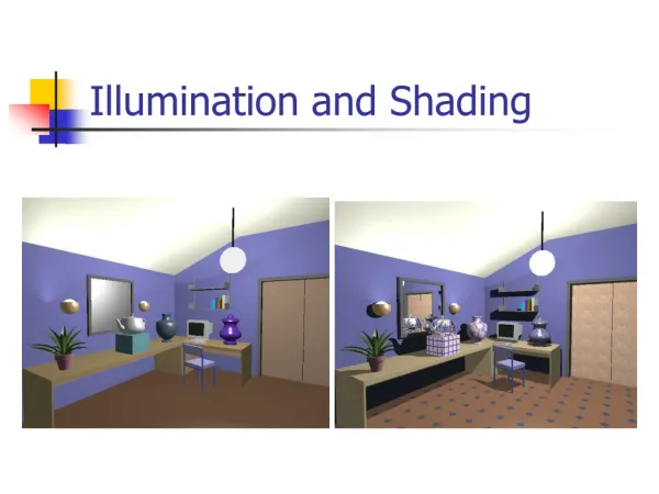
This lecture focuses on local illumination and shading techniques in computer graphics, emphasizing how to calculate the color of objects based on various factors such as incident light, light source position, object reflectance, and viewer position. Key topics include the ambient, diffuse, and specular components of lighting, along with the Phong Illumination Model. The lecture covers different shading models, including flat shading, Gouraud shading, and Phong shading, exploring their computational requirements and visual results to enhance rendering in real-time graphics applications.

E N D
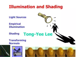
Local Illumination and Shading Computer Graphics – Lecture 3 Taku Komura tkomura@ed.ac.uk Institute for Perception, Action & Behaviour
Today is about calculating the color of objects • The incident light • Position of light source • Direction • Color The object • Reflectance Viewer • Position
Overview • Illumination (how to calculate the colour) • Shading (how to colour the whole surface)? • BRDF (how to simulate the reflection of real objects)
Illumination • Simple 3 parameter model • The sum of 3 illumination terms: • Ambient : 'background' illumination • Specular : bright, shiny reflections • Diffuse : non-shiny illumination and shadows 'Virtual' camera = + + Rc Specular (highlights) Ambient (colour) Diffuse (directional)
Ambient Lighting • Light from the environment • light reflected or scattered from other objects • Coming uniformly from all directions • and then reflected equally to all directions • simple approximation to complex 'real-world' process • Result: globally uniform colour for object • I = resulting intensity • Ia= light intensity • ka = reflectance Example: sphere Object
Object Diffuse Lighting • Light reflected to all directions • considers the angle of incidence of light on surface • (angle between light and surface normal) • Also known as Lambertian reflection • Result: lighting varies over surface with orientation to light Ln Infinite point light source Example: sphere (lit from left) N I No dependence on camera angle!
Object Specular Lighting • Direct reflections of light source off shiny object • specular intensity n = shiny reflectance of object • Result: specular highlight on object Ln N Infinite point light source R (Reflection) α Ip: light intensity I : output color R: reflection vector S: direction towards the camera α : angle between R and S No dependence on object colour.
Combined Lighting Models • Summing it altogether : Phong Illumination Model = + + Rc Specular (highlights) Ambient (colour) Diffuse (directional)
Object When you implement it… Use dot product of the vectors instead of calculating the angles N R L α V : Vector from the surface to the viewer : Normal vector at the colored point : Normalized reflection vector : Normalized vector from the coloured point towards the light source
Demo applets • http://www.cs.auckland.ac.nz/~richard/research-topics/PhongApplet/PhongDemoApplet.html
Local Illumination Model • Considers light sources and surface properties only. • Not considering the light reflected back onto other surfaces • Fast real-time interactive rendering. • Most real-time graphics (games, virtual environments) are based on local illumination models • Implementation - OpenGL, Direct3D
Attenuation • Haven’t considered light attenuation – the light gets weaker when the object is far away • Use 1/(s+k) where s relates to eye-object distance and k is some constant for scene. • Note: must apply 3 times – for each primary colour
Color • Finally color the pixel by the RGB color
Overview • Illumination (how to calculate the color) • Shading (how to color the whole surface)?
How often do we do the computation of illumination? • At all the points on the surface? • But usually we have normals only at the vertices Depends on the shading model – Flat Shading (once per polygon) (less computation needed) – Gouraud shading (once per vertex) – Phong Shading (once per pixel) (heavy computation needed)
Flat Shading • Compute the colour at the middle of the polygon • All points in the same polygon are coloured bythe same colour
Shading Polyhedra • Flat (facet) shading: • Works well for objects really made of flat faces. • Appearance depends on number of polygons for curved surface objects. • If polyhedral model is an approximation then need to smooth.
Mach banding. • Physiological effect exaggerates difference between closely coloured polygons. • Mach banding. • Exaggerates intensity change at an edge with a discontinuity in magnitude. • Our eyes are well adapted to seeing edges ! • Using a finer mesh is surprisingly ineffective.
Gouraud Shading (Smooth Shading) • Compute the color at each vertex first • Compute the color inside the polygon by interpolating thecolors of the vertices composing the polygon
Gouraud Shading. Find vertex normals by averaging face normals • - Use vertex normals with desired shading model, • Interpolate vertex intensities along edges. • Interpolate edge values across a scanline. B A Ibc Iac Iac interpolated A to C, Ibc interpolated B to C. C
Phong Shading • interpolating the normal vectors at the vertices • Do the computation of illumination at each point in thepolygon
Direction of maximum highlight Phong shading. • For specular reflection, highlight falls off with cosn • Gouraud shading linear interpolates – makes highlight too big. • Gouraud shading may well miss a highlight that occurs in the middle of the face.
Direction of maximum highlight Highlight on surface. Phong shading. • In Phong model of specular reflection, highlight falls off with cosn • Gouraud shading linear interpolates – makes highlight too big. • Gouraud shading may well miss a highlight that occurs in the middle of the face.
Gouraud Shaded Floor Phong Shaded Floor • Gouraud shading is not good when the polygon count is low
A C B Problems with interpolation shading. • Problems with computing vertex normals. • A,B are shared by all polygons, but C is not shared by the polygon on the left. • Shading information calculated to the right of C will be different from that to the left. • Shading discontinuity. Solution 1: subdivide into triangles that that share all the vertices Solution 2 : introduce a ‘ghost’ vertex that shares C’s values
Problems with interpolation shading. • Problems with computing vertex normals. Face surface normals and averaged vertex normals shown. Unrepresentative so add small polygon strips along edges or test angle and threshold to defeat averaging.
A B A D B D C Problems with interpolation shading. • Rotational invariance? • When interpolating the colour inside a polygon, the edge colours are determined first, and then they are interpolated to compute the internal colour • If the number of edges is >= 4, the results of interpolation shading can change with orientation of the polygon. Point on left is interpolated between AD & AB , Point on right is interpolated between AB & BC C
Problems with interpolation shading. • Solution. • Decompose polygon into triangles before Gouraud shading.
Overview • Illumination (how to calculate the color) • Shading (how to color the whole surface)? • BRDF (how to simulate the reflection of real objects)
What about real objects? • Phong Illumination model is popular but actually it is not accurate • True photorealism, requires more sophisticated and elaborate models of surface properties
Reflectance of objects • The way the light reflects depends on the physical characteristics of the surface • Its not uniform
Bidirectional Reflectance Distribution Function (BRDF) • The reflectance of an object can be represented by a function of the incident and reflected angles • This function is called the Bidirectional Reflectance Distribution Function (BRDF) • where E is the incoming irradianceand L is the reflected radiance
What affects the BRDF? • The way light reflecting over the surface • The smoothness/roughness of the surface • Single reflection : if smooth, specular • Multiple reflections : diffusive • The shadowing effect
Isotropic and Anisotropic BRDFs • Isotropic: • Can model by diffuse + specular reflection • Anisotripic • Brushed metal • Cannot model by diffuse + specular reflection • Reflectance changing systematically with respect to direction
Measuring the BRDF • Measured using a device called gonioreflectometer • Casting light from various directions to the object, and capturing the light reflected back
Summary • Illumination model • Phong model • Shading • Flat, • Gouraud, • Phong Shading • BRDF • Measuring
Recommended Reading • Foley et al. Chapter 16, sections 16.1.6 up to and including section 16.3.4. • Introductory text Chapter 14, sections 14.1.6 up to and including section 14.2.6.